Broad pressure and frequency range accumulator

a frequency range and accumulator technology, applied in the direction of gas/liquid distribution and storage, cleaning of hollow articles, water supply installation, etc., can solve the problems of accumulator this range can be quite limited, the accumulator may fail, and the ureter or diaphragm may fail

Inactive Publication Date: 2012-10-25
RESONANCE TECH INT
View PDF20 Cites 13 Cited by
  • Summary
  • Abstract
  • Description
  • Claims
  • Application Information

AI Technical Summary

Benefits of technology

[0015]In accordance with another aspect of the present invention, there is provided a resonant vibratory system comprising: a working fluid system comprising one or more conduits, the working fluid system configured to contain hydraulic fluid, the working fluid system comprising an accumulator coupling location; a power source operatively coupled to the working fluid system and configured to drive said hydraulic fluid in the working system; a power delivery system operatively coupled to the working fluid system and configured to deliver resonant vibratory power to a load; and an accumulator apparatus comprising: a pressure vessel having inner walls defining an elongated cavity, the pressure vessel comprising a communication port in fluid communication with a first portion of the elongated cavity, the communication port operatively coupled to the working fluid system at the accumulator coupling location, the pressure vessel further comprising an energy storage and return portion associated with a second portion of the elongated cavity; and a piston assembly located within the elongated cavity and configured to separate the elongated cavity into the first portion and the second portion, the piston assembly comprising: a diaphragm; and a ring portion operatively coupled to the diaphragm at an outer periphery of the diaphragm, the ring portion movably and sealingly engaged with said inner walls; wherein the diaphragm is configured to deform under a pressure differential between the cavity first portion and the cavity second portion, thereby developing a tensile force within the diaphragm, the outer periphery of the diaphragm configured to transfer a force representative of the tensile force into the ring portion, the ring portion configured to move within the elongated cavity at least in part in response to said force.

Problems solved by technology

For a diaphragm or bladder style accumulator this range can be quite limited.
If the operating pressure deviates from an acceptable range, the bladder or diaphragm may fail.
The failure mechanism for this situation can be due to pressure rising above an acceptable range and over stressing the membrane, or decreasing to a level where the membrane can come in contact with hazardous components of the device causing damage.
Both risk damage to the gas retention fabric at highly cyclic loading which is exacerbated at low operating pressures by beating of the plate against the orifice opening or repeated opening and closing of the valve.
However, the piston itself is typically substantially larger and more massive than a bladder or diaphragm.
This can cause the piston to be inherently slow and unable to react to a high frequency pressure fluctuation.
The limits of the piston's reaction time eliminate the effectiveness of the piston style accumulator for certain devices which operate in higher frequency domains.
However, for resonant vibratory systems, pressure fluctuations may occur regularly or cyclically, with a need for a dampening effect on every cycle of the vibration.
At these frequencies the mass of a conventional piston style accumulator may make it too slow to effectively reduce the pressure fluctuations in the system.
For example, when operating in different conditions or in order to obtain resonance, a certain amount of time may be required in which these devices are running off-resonance.
Conventional bladder or diaphragm style accumulators may not be appropriate for dealing with such large pressure ranges.
For example, the gas pre-charge level may not be sufficiently adjustable in such accumulators to offer a large enough range for safe deflection of the membrane, which may thus lead to membrane failure.
With no accumulator, excess pressure fluctuations in working fluid may cause damage to many parts of these vibrators such as seals, ports, pumps etc.
However, this device leaves evident failure mechanisms which would prevent sustained life of the deflectable diaphragm.
Thus, the nature of the device results, under normal operating conditions, in repeated and cyclical contact made between the fragile diaphragm and caged assembly quickly causing damage to the diaphragm and eventual failure.
In addition, use of materials such as Teflon™ for the flexible diaphragm, as taught by U.S. Pat. No. 4,307,753, may not provide for adequate performance of the pulsation dampener device in some applications.

Method used


Image

  • Broad pressure and frequency range accumulator
  • Broad pressure and frequency range accumulator
  • Broad pressure and frequency range accumulator

Examples


example 1

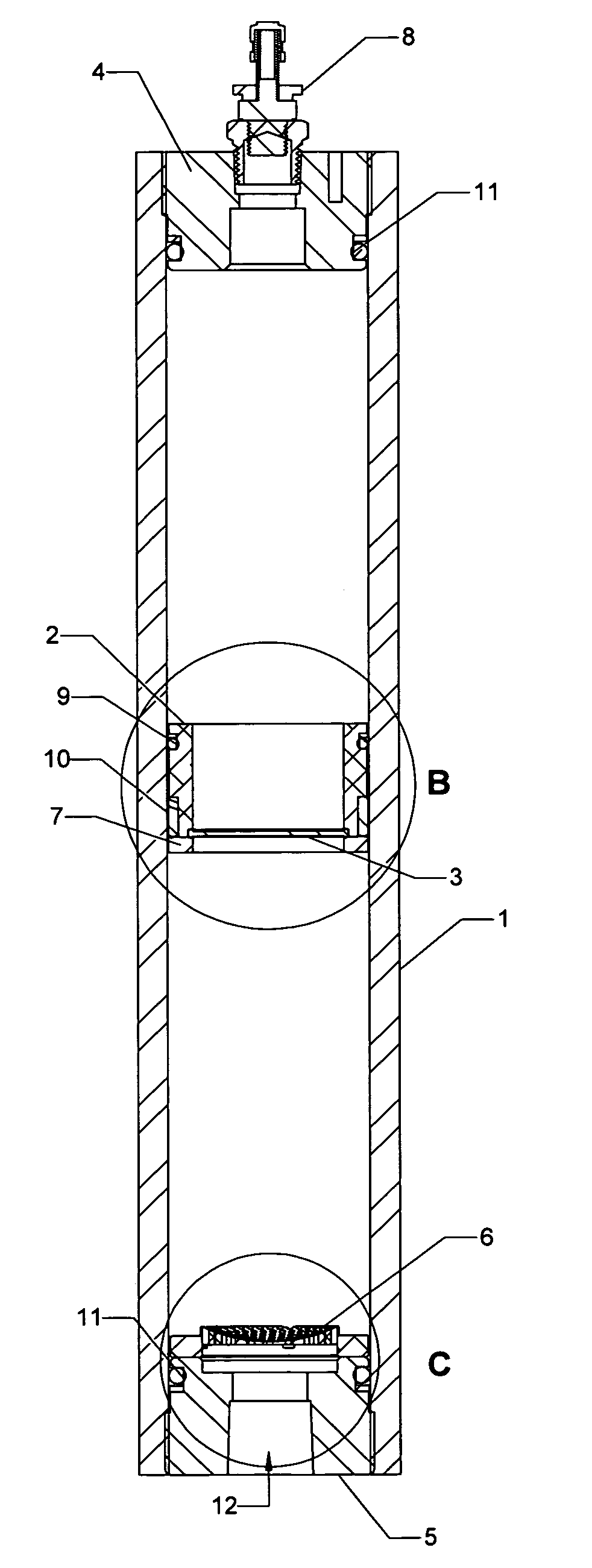
[0059]Now referring to FIGS. 3 to 6, an accumulator in accordance with an exemplary embodiment of the present invention will be described with relevant components and possible alternative components. FIG. 3 shows an external view of the accumulator comprising a cylindrical pressure vessel. The shape and dimensions of the pressure vessel may be adjusted depending on desired operational characteristics of the accumulator. The elongated, cylindrical shape facilitates travel of the piston assembly in an elongated cavity of the pressure vessel, in order to tend to equalize pressures between first and second portions of the elongated cavity separated by the piston assembly. The pressure vessel comprises a honed cylinder 1 of material capable of withstanding the pressures required. In some embodiments, the pressure vessel comprises steel honed seamless mechanical tubing. This material is readily available in a variety of situations and may simplify the design without the need for a custom ...

example 2

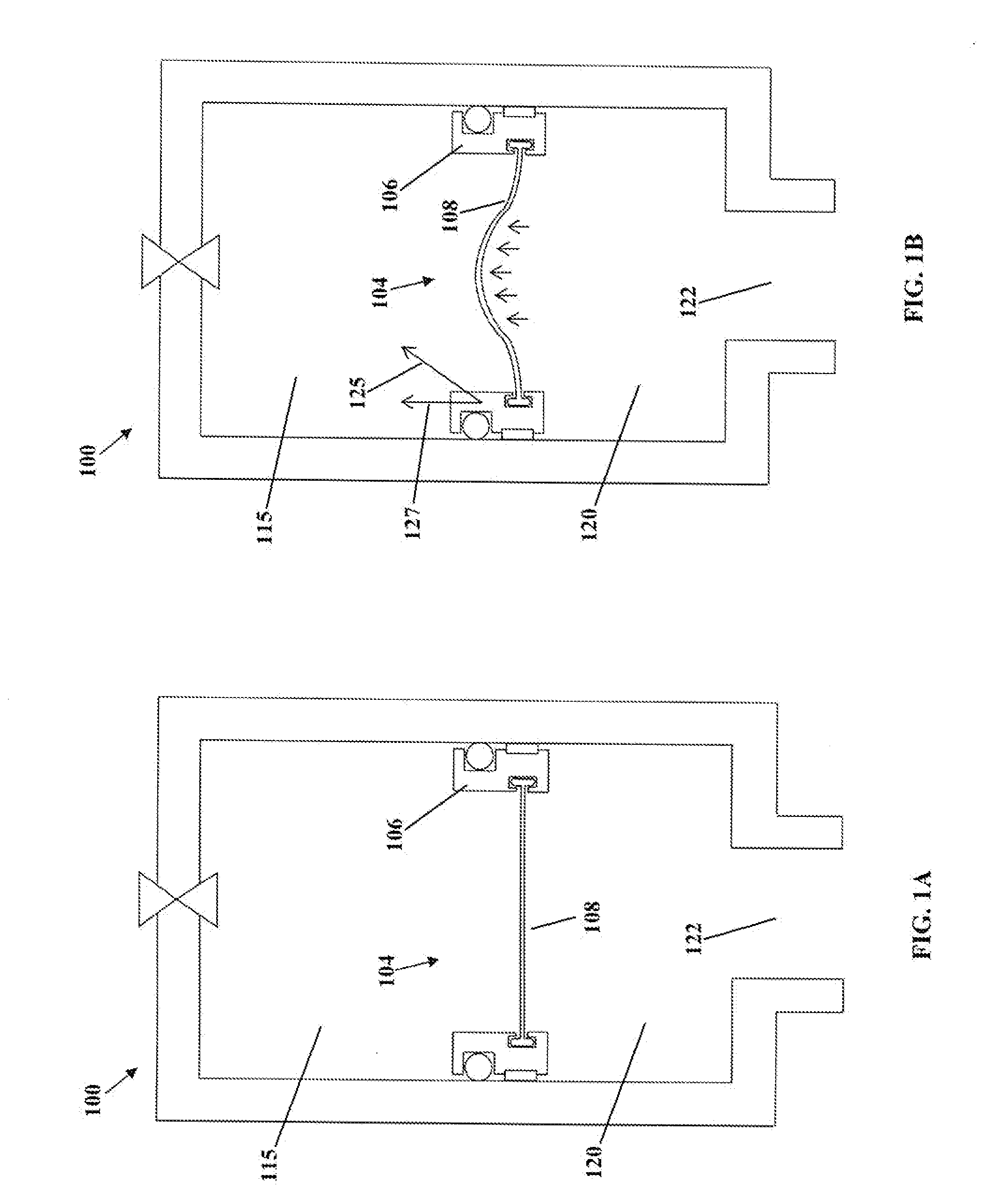
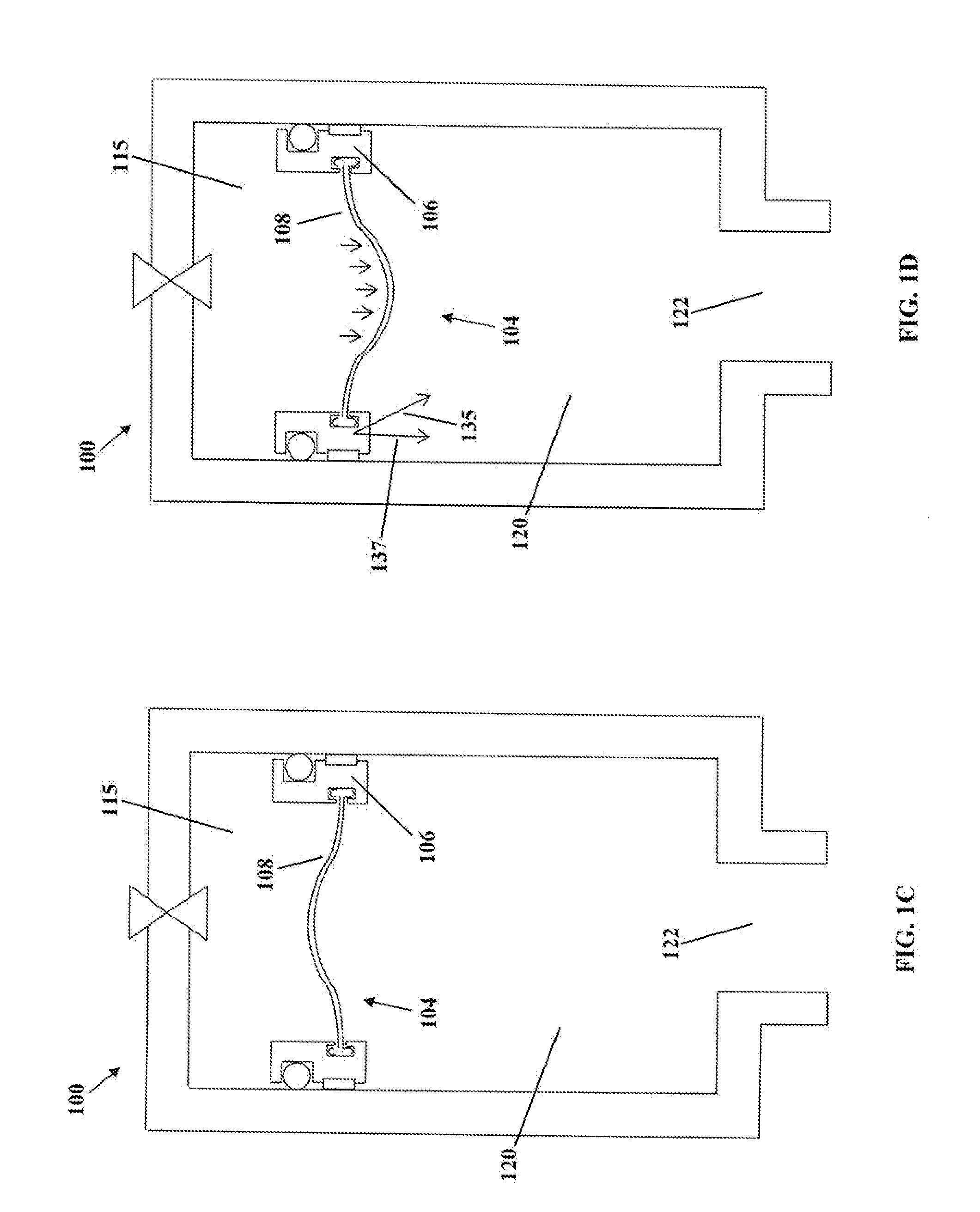
[0066]In an exemplary application, an accumulator in accordance with an embodiment of the present invention is installed into a device that requires the suppression of pressure fluctuations over a wide pressure range and at high frequencies. Specifically it may be operatively coupled to a working fluid system of one or more items of resonant vibratory equipment such as pile drivers, drills, and compactors which operate both off and on resonance and therefore operate under varying pressure conditions.

[0067]The accumulator may be installed in a substantially vertical position, and operatively coupled to a working fluid system on the pressure side of the flow of working fluid. The accumulator may be installed close to the main inlet or outlet of working fluid and in direct communication with the fluid flow. In some embodiments, the less tortuous the fluid path communicating the accumulator to the flow, the more effective the accumulator will be. This accumulator may comprise an externa...


PUM

PropertyMeasurementUnit
natural frequenciesaaaaaaaaaa
frequencyaaaaaaaaaa
frequencyaaaaaaaaaa

Abstract

A method and apparatus for reducing undesirable pressure fluctuations over predetermined pressure and frequency ranges in a working fluid system, facilitating maintenance of appropriate levels of stored energy in the fluid system. Embodiments may be employed within a fluid system to dampen pressure fluctuations over an adequately large pressure range, for example in a resonant vibratory system. In such systems, pressures vary dramatically depending on whether resonance is achieved. An apparatus comprises a pressure vessel having a self equilibrating flexible piston device. The piston separates a gas volume from a fluid volume exposed to the system flow. The piston translates within the pressure vessel to equilibrate the gas and fluid pressures. A flexible portion of the piston deflects at high frequency and adequate volume to reduce undesirable pressure fluctuations. The flexible portion translates force via its outer periphery to a ring portion which translates within the pressure vessel.

Description

FIELD OF THE INVENTION[0001]The present invention pertains in general to hydraulic or fluid accumulators and in particular to a broad pressure and frequency range accumulator.BACKGROUND[0002]Devices which are capable of removing undesirable pressure fluctuations in fluid, typically hydraulic, systems are used in a variety of forms. Common names of these devices are accumulators, suppressors and dampening devices. These devices may function to store energy so as to smooth pressure pulses and reduce transverse effects on system components, thereby extending the life of the fluid system. Conventional gas-charged accumulator devices include a component which separates the hydraulic working fluid from a compressible gas, such as a piston, diaphragm, or bladder which is able to deflect due to the rise in working fluid pressure, compressing the gas volume trapped behind. The compression of the gas volume then stores energy which is returned to the system when the working fluid pressure is ...

Claims


Application Information

Patent Timeline
Patent Type & Authority Applications(United States)
IPC IPC(8): F15B1/027B23P11/00F16L55/02
CPCF15B1/14F15B2201/205F15B2201/312Y02E60/15F15B1/10F15B1/24F15B2201/31F15B2201/3151Y02E60/16Y10T137/0402
Inventor JANES, MATTHEW C.REELIE, DOUGLAS D.VANSICKLE, BRADLEY E.PAGE, STEWART G.
Owner RESONANCE TECH INT
Why Eureka
Try Eureka