Magnetic stacks with perpendicular magnetic anisotropy for spin momentum transfer magnetoresistive random access memory

a random access memory and magnetic anisotropy technology, applied in the field of spin momentum transfer magnetoresistive random access memory (mram), can solve the problems of difficulty in reading operations in the stt mram and low mr of mtjs made using pma materials

Inactive Publication Date: 2012-10-25
IBM CORP
View PDF3 Cites 110 Cited by
  • Summary
  • Abstract
  • Description
  • Claims
  • Application Information

AI Technical Summary

Benefits of technology

[0006]In one aspect, a magnetic tunnel junction (MTJ) for a magnetic random access memory (MRAM) includes a magnetic free layer, having a variable magnetization direction; an insulating tunnel barrier located adjacent to the free layer; a magnetic fixed layer having an invariable magnetization direction, the fixed layer disposed adjacent the tunnel barrier such that the tunnel barrier is located between the free layer and the fixed layer, wherein the free layer and the fixed layer have perpendicular magnetic anisotropy; and one or more of: a composite fixed layer, the composite fixed layer comprising a dusting layer, a spacer layer, and a reference layer, wherein the spacer layer is located between the reference layer and the tunnel barrier, and wherein the dusting layer is located between the spacer layer and the tunnel barrier; a synthetic antiferromagnetic (SAF) fixed layer structure, the SAF fixed layer structure comprising a SAF spacer located between the fixed layer and a second fixed magnetic layer, wherein the fixed layer and the second fixed magnetic layer are anti-parallely coupled through the SAF spacer; and a dipole layer, wherein the free layer is located between the dipole layer and the

Problems solved by technology

However, MTJs made using PMA materials may have a relatively low MR because of structural and chemical incompatibility between the various material layers that comprise a PMA MTJ.
A relatively low MR may result in difficulty with read operations in the STT MRAM, as the difference in resis

Method used


Image

  • Magnetic stacks with perpendicular magnetic anisotropy for spin momentum transfer magnetoresistive random access memory
  • Magnetic stacks with perpendicular magnetic anisotropy for spin momentum transfer magnetoresistive random access memory
  • Magnetic stacks with perpendicular magnetic anisotropy for spin momentum transfer magnetoresistive random access memory

Examples


Embodiment Construction

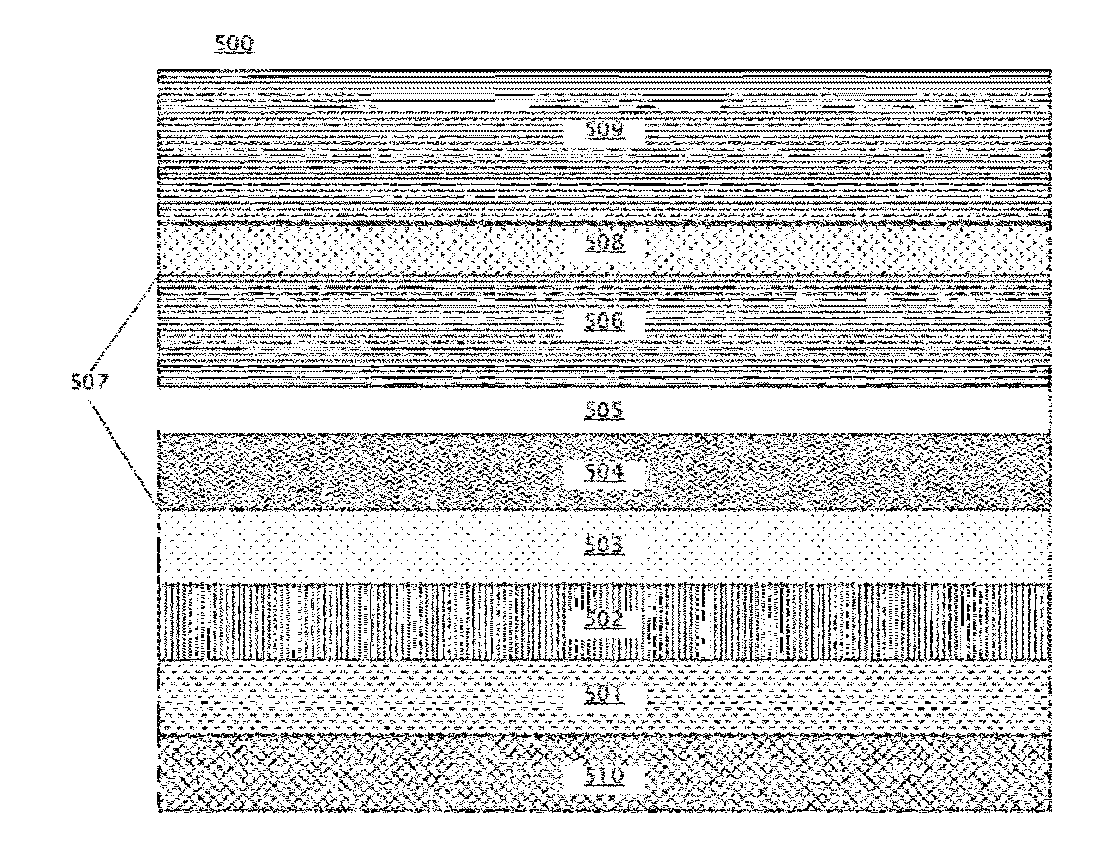
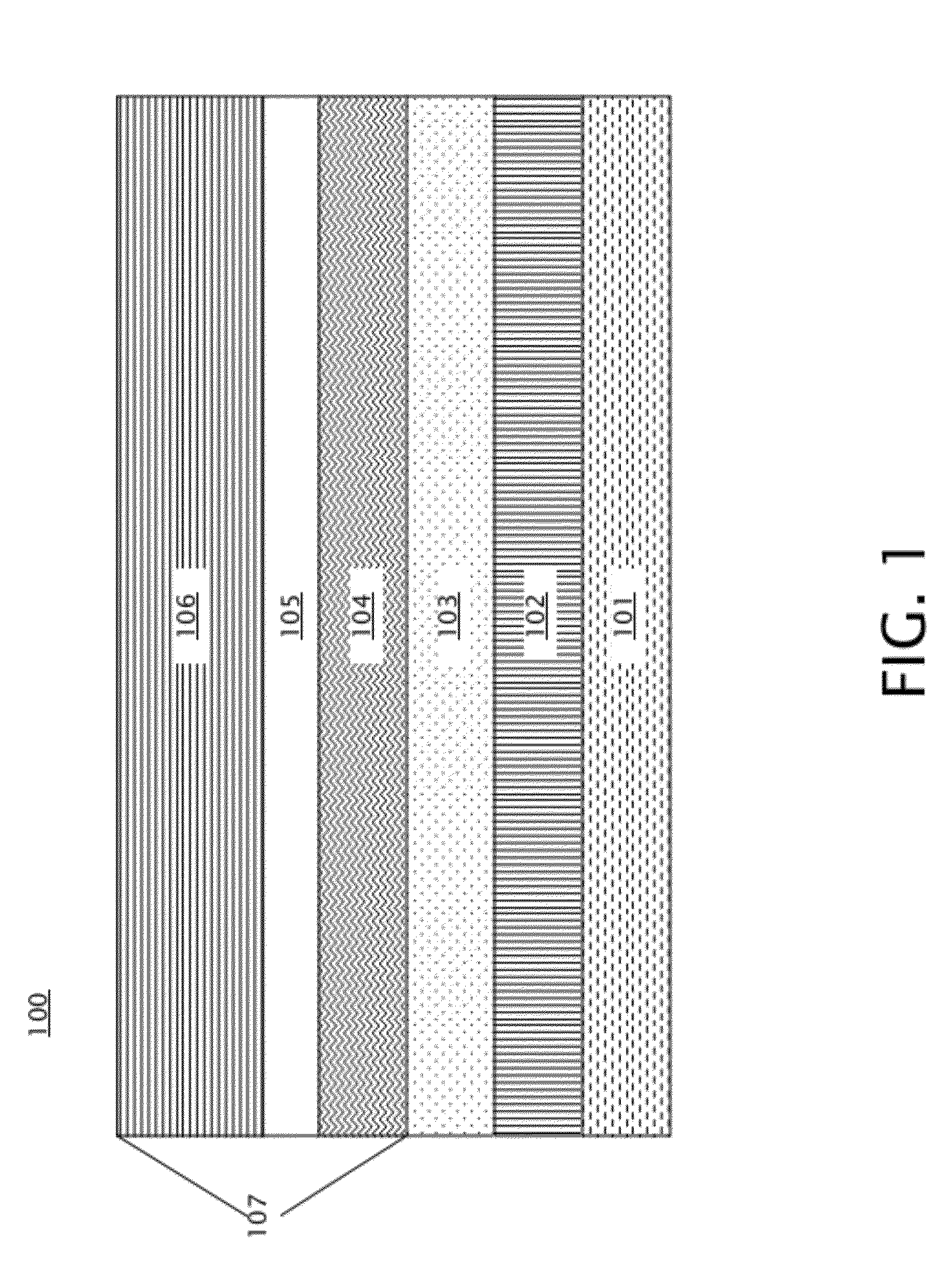
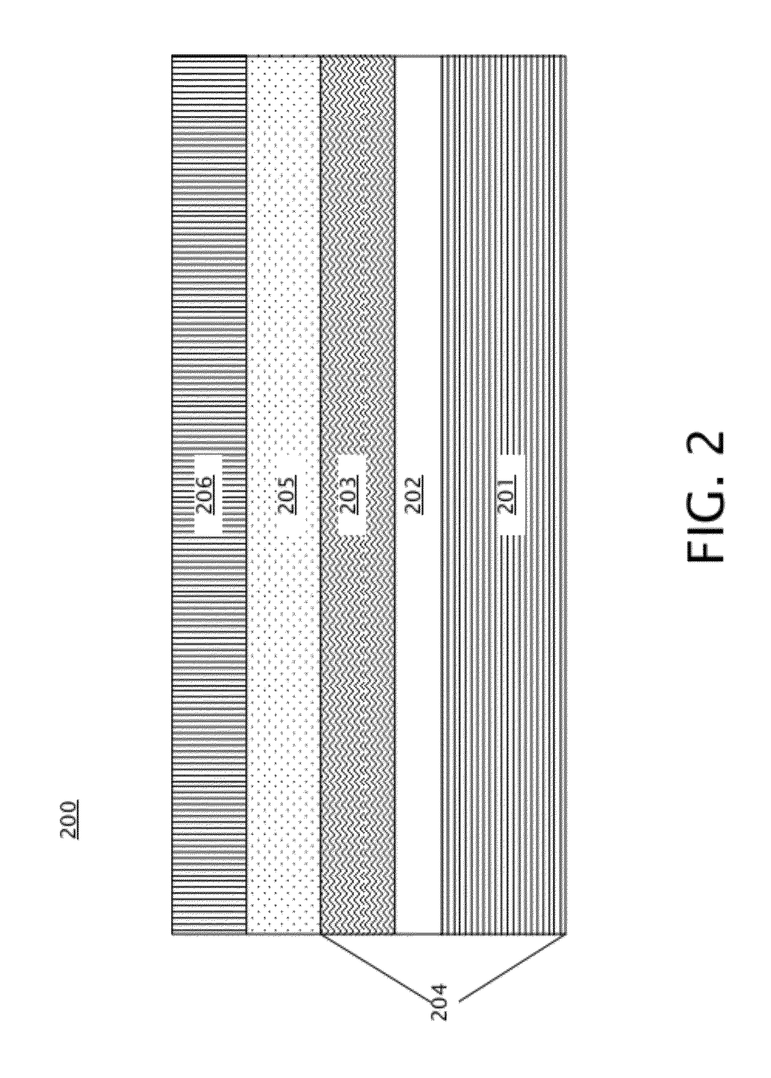
[0018]Embodiments of PMA magnetic stacks for STT MRAM are provided, with exemplary embodiments being discussed below in detail. The PMA magnetic stacks form MTJs that exhibit a high MR and a reduced fixed layer dipolar field thus commensurately reduced free layer loop offset through inclusion of one or more of a composite fixed layer, a synthetic antiferromagnetic (SAF) structure in the fixed layer, and a dipole layer. A composite fixed layer includes three layers: a dusting layer, a spacer layer, and a reference layer. A fixed layer SAF structure includes a SAF spacer located between two layers of magnetic material that are anti-parallelly coupled through the SAF spacer. The magnetization of the two layers of magnetic material in the SAF structure may be adjusted such that they are aligned opposite to one another, reducing the overall fixed layer dipole field. A dipole layer is located on the opposite side of the free layer from the tunnel barrier, and may be magnetized in a direct...


PUM


Abstract

A magnetic tunnel junction (MTJ) includes a magnetic free layer, having a variable magnetization direction; an insulating tunnel barrier located adjacent to the free layer; a magnetic fixed layer having an invariable magnetization direction, the fixed layer disposed adjacent the tunnel barrier such that the tunnel barrier is located between the free layer and the fixed layer, wherein the free layer and the fixed layer have perpendicular magnetic anisotropy; and one or more of: a composite fixed layer, the composite fixed layer comprising a dusting layer, a spacer layer, and a reference layer; a synthetic antiferromagnetic (SAF) fixed layer structure, the SAF fixed layer structure comprising a SAF spacer located between the fixed layer and a second fixed magnetic layer; and a dipole layer, wherein the free layer is located between the dipole layer and the tunnel barrier.

Description

BACKGROUND[0001]This disclosure relates generally to the field of magnetoresistive random access memory (MRAM), and more specifically to spin momentum transfer (SMT) MRAM.[0002]MRAM is a type of solid state memory that uses tunneling magnetoresistance (MR) to store information. MRAM is made up of an electrically connected array of magnetoresistive memory elements, referred to as magnetic tunnel junctions (MTJs). Each MTJ includes a magnetic free layer having a magnetization direction that is variable, and a magnetic fixed layer having a magnetization direction that is invariable. The free layer and fixed layer are separated by an insulating non-magnetic tunnel barrier. An MTJ stores information by switching the magnetization state of the free layer. When the magnetization direction of the free layer is parallel to the magnetization direction of the fixed layer, the MTJ is in a low resistance state. When the magnetization direction of the free layer is anti-parallel to the magnetizat...

Claims


Application Information

Patent Timeline
IPC IPC(8): H01L29/82H01L21/8239
CPCG11C11/16H01L43/12H01L43/10H01L43/08G11C11/161H10N50/85H10N50/01H10N50/10G11B5/39
Inventor HU, GUOHANNOWAK, JANUSZ J.TROILLOUD, PHILIP L.WORLEDGE, DANIEL C.
Owner IBM CORP
Why Eureka
Try Eureka