Dual-Sensor Temperature Stabilization for Integrated Electrical Component

a technology of integrated electrical components and temperature stabilization, which is applied in the direction of generator stabilization, electrostatic generators/motors, impedence networks, etc., can solve the problems of large devices, low integration level of the system using quartz reference, and less stable frequency characteristic over temperature than the effect of temperature control

Inactive Publication Date: 2012-10-25
INTERUNIVERSITAIR MICRO ELECTRONICS CENT (IMEC VZW)
View PDF1 Cites 27 Cited by
  • Summary
  • Abstract
  • Description
  • Claims
  • Application Information

AI Technical Summary

Benefits of technology

[0006]It is an aim of the present invention to provide a system and a method for stabilizing a temperature of an integrated electrical component at a predefined temperature (Tset), which are less complex.

Problems solved by technology

However, such quartz device is large and a system using a quartz reference suffers from a low level of integration.
However, MEMS resonators without compensation show a high sensitivity of frequency drift over temperature (e.g. +−5000 ppm over a 100° C. ambient temperature range), and thus have a less stable frequency characteristic over temperature than a quartz crystal, as illustrated in FIG. 2.
A problem however with these mechanisms is the accuracy and temperature stability of the temperature sensors themselves.
Their own drift over temperature limits the achievable temperature stability of the MEMS resonator, which is why a reliable (and expensive) temperature reference is often needed in such systems.
This concept however has the disadvantage of requiring two resonators with a different temperature coefficient of frequency (TCF), requiring a lot of chip-area.
Also, to achieve the desired frequency, the temperature at both resonator bars should be identical, which may be conceptually easy by matching the designs, but in practice very hard to guarantee.

Method used


Image

  • Dual-Sensor Temperature Stabilization for Integrated Electrical Component
  • Dual-Sensor Temperature Stabilization for Integrated Electrical Component
  • Dual-Sensor Temperature Stabilization for Integrated Electrical Component

Examples


Embodiment Construction

References

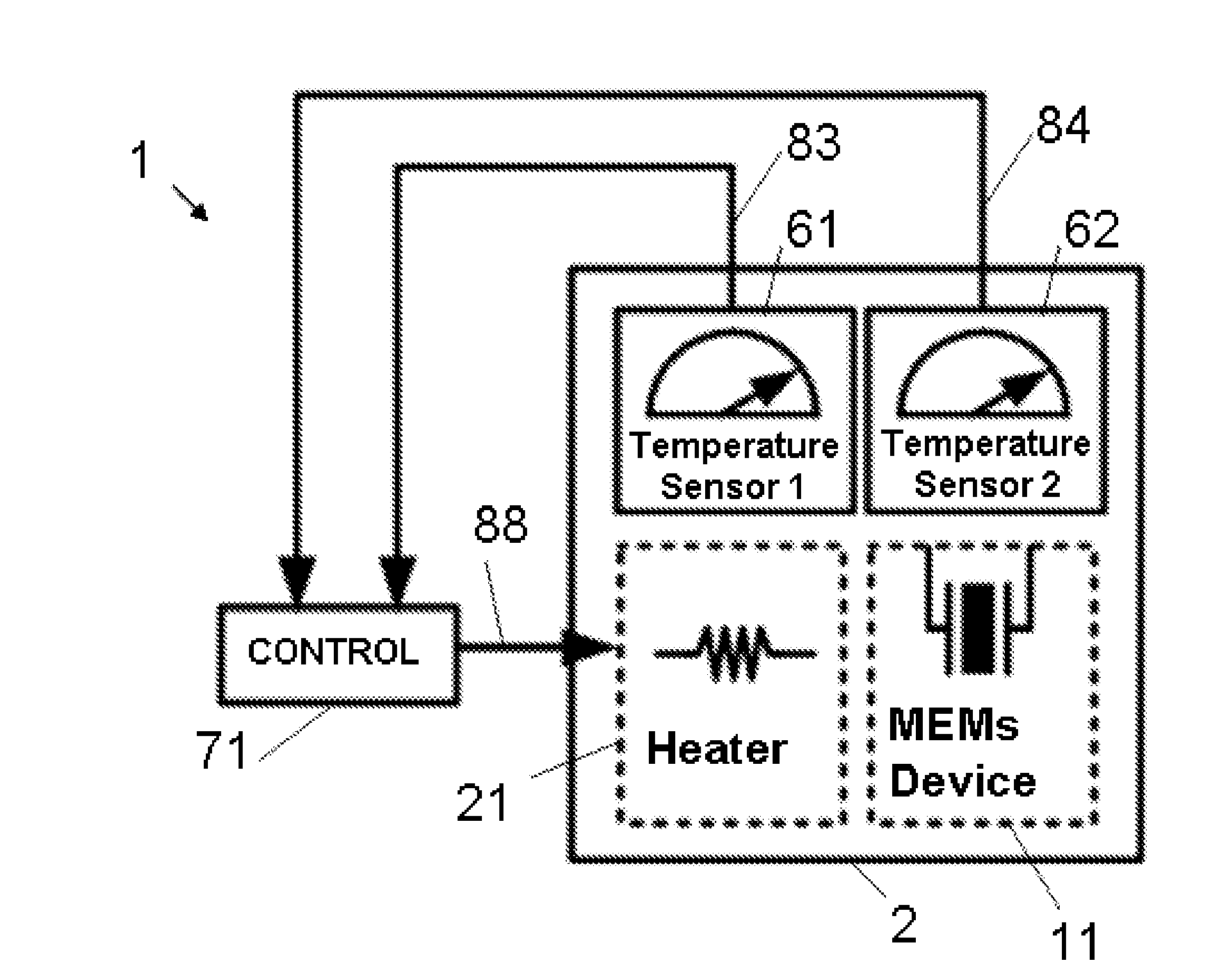
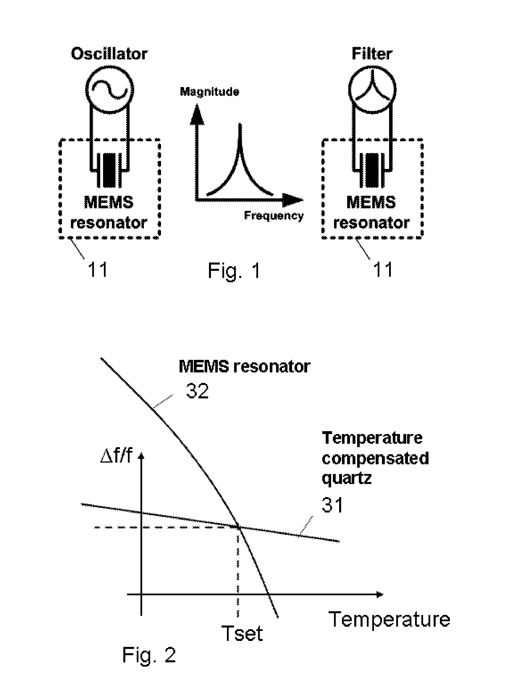
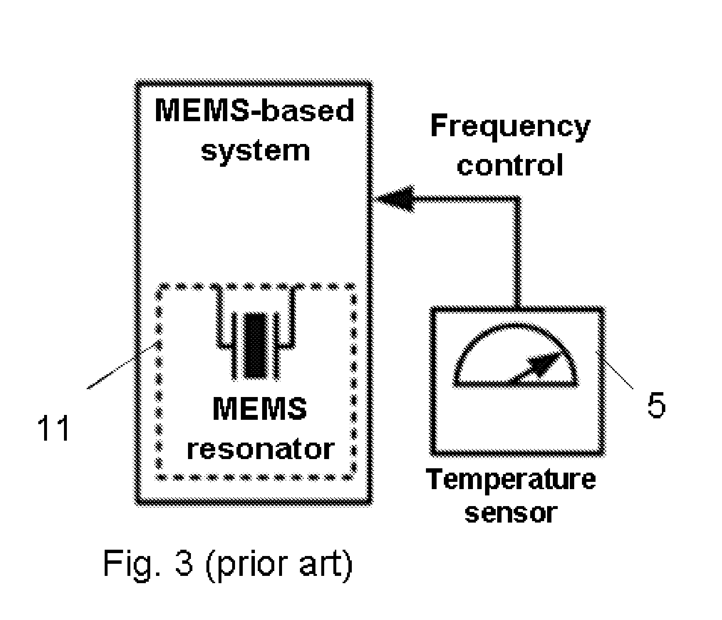
[0055]1 system[0056]11 MEMS structure, MEMS component, MEMS device[0057]2 oven[0058]21 heater, heating means[0059]22 vacuum package[0060]31 frequency curve of a temperature compensated quartz crystal versus temperature[0061]32 frequency curve of an uncompensated MEMS resonator versus temperature[0062]5 temperature sensor[0063]6 reference temperature sensor[0064]61 first sensing element[0065]62 second sensing element[0066]63 temperature dependent characteristic of first sensing element[0067]64 temperature dependent characteristic of second sensing element[0068]65 intersection point[0069]7 electrical device[0070]71 control circuit[0071]81 first sensing signal[0072]82 second sensing signal[0073]83 first measurement signal[0074]84 second measurement signal[0075]85 difference signal[0076]86 comparison signal[0077]87 output signal[0078]88 control signal[0079]90 post compensation circuit[0080]91 post compensation signal[0081]92 output signal including post-compensation[0082]Toven...


PUM


Abstract

Method and system (1) for stabilizing a temperature (Tcomp) of an integrated electrical component, placed in an oven, at a predefined temperature (Tset). The temperature of the integrated electrical component is sensed by means of temperature sensing means, comprising a first resp. second sensing element (61, 62) located in good thermal contact with the integrated electrical component, the first resp. second sensing elements (61, 62) having a first resp. second temperature dependent characteristic (63, 64), the second temperature dependency being different from the first temperature dependency such that the first and second characteristics (63, 64) intersect at the predefined temperature (Tset), and a sensing circuit (72) adapted for sensing the first and the second sensing elements (61, 62) and for supplying a first resp. second measurement signal (83, 84) indicative of the first resp. second temperature dependent characteristics (63, 64) to a control circuit (71), which determines a control signal for the heating means therefrom.

Description

TECHNICAL FIELD[0001]The present invention relates generally to a temperature control system, in particular to an ovenized dual-sensor control system and a method for stabilizing the temperature for an integrated electrical component.BACKGROUND ART[0002]It is known that Micro-electromechanical systems (MEMS) and in particular MEMS resonators possess a very high quality factor (Q), and can be used to build oscillators, which makes them viable to serve as frequency reference devices, as illustrated in FIG. 1. Traditionally however quartz crystals are often used as a frequency reference because of their better temperature stability. When higher stability is required, such as in broadcast transmitter systems, an oven controlled crystal oscillator is often used. However, such quartz device is large and a system using a quartz reference suffers from a low level of integration. MEMS oscillators on the other hand are small, and can be integrated, thus lowering the cost significantly. Howeve...

Claims


Application Information

Patent Timeline
Patent Type & Authority Applications(United States)
IPC IPC(8): H03L1/04H02N1/00
CPCG05D23/1928H03H9/02448H03H3/0076
Inventor BORREMANS, JONATHAN
Owner INTERUNIVERSITAIR MICRO ELECTRONICS CENT (IMEC VZW)
Why Eureka
Try Eureka