Switchgear unit for switching high DC voltages

a switchgear unit and high dc voltage technology, applied in the direction of electrical equipment, basic electric elements, heating/cooling contact switches, etc., can solve the failure of the switchgear unit, the connection between the conductor section and the contact system at the melting location is broken, and the isolating apparatus is tripped, etc., to achieve fast extinguishing of the second arc, the effect of safe touch and fast ionization

Active Publication Date: 2012-10-25
ELLENBERGER & POENSGEN GMBH
View PDF36 Cites 11 Cited by
  • Summary
  • Abstract
  • Description
  • Claims
  • Application Information

AI Technical Summary

Benefits of technology

[0018]The thermal fuse in the switchgear unit therefore serves as a failsafe element which is suitable particularly for use in PV installations. In addition, the backup for the switchgear unit is inexpensive to manufacture and therefore meets the requirements of economic manufacturability.
[0037]The interaction with the choice of suitable plastics for housing, insulating chamber and isolating element, the shape and the material of the contact carrier and the dimensioning of the squeezing-in and also the torque acting on the melting location allow exact tripping of the isolating apparatus in the event of a fault and reliable extinguishing of the arc.

Problems solved by technology

The isolating apparatus is tripped and the connection between the conductor section and the contact system at the melting location is broken when the arc has caused the melting temperature of the melting location to be reached or exceeded.
This results in a failsafe for the switchgear unit, which is tripped or has a fault detected independently of current level.

Method used


Image

  • Switchgear unit for switching high DC voltages
  • Switchgear unit for switching high DC voltages
  • Switchgear unit for switching high DC voltages

Examples


Embodiment Construction

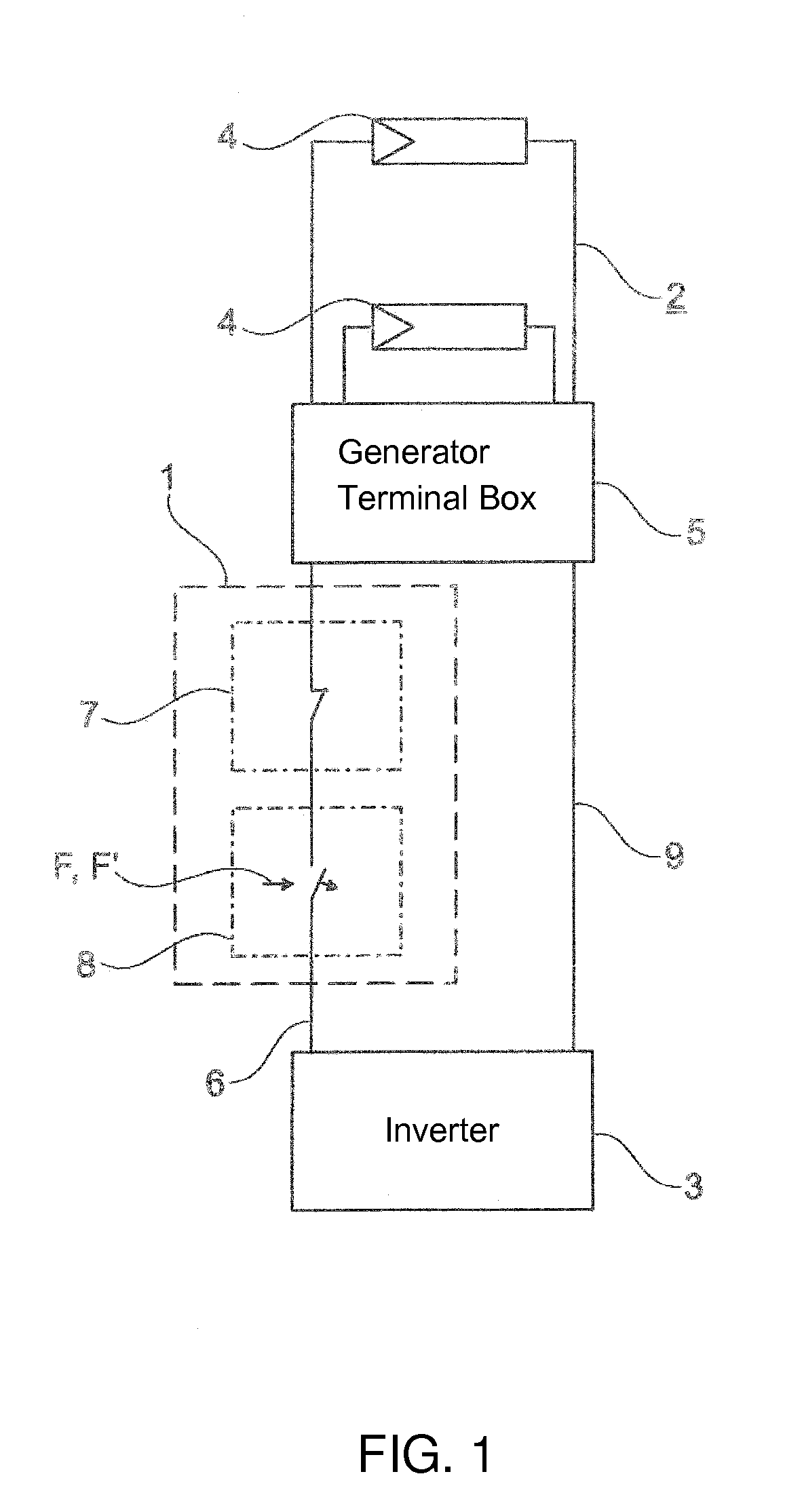
[0052]Parts and magnitudes which correspond to one another have always been provided with the same reference symbols in all figures. Referring now to the figures of the drawing in detail and first, particularly, to FIG. 1 thereof, there is shown schematically a switchgear unit 1 which, in the exemplary embodiment, is connected between a PV generator 2 and an inverter 3. The PV generator 2 contains a number of solar modules 4 which are directed, in a situation parallel to one another, to a common generator terminal box 5, which effectively serves as an assembly point.

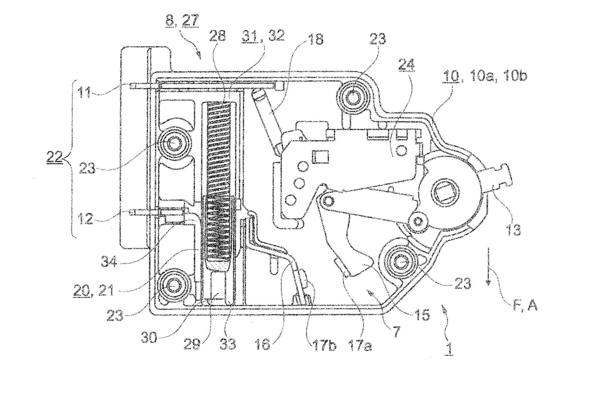
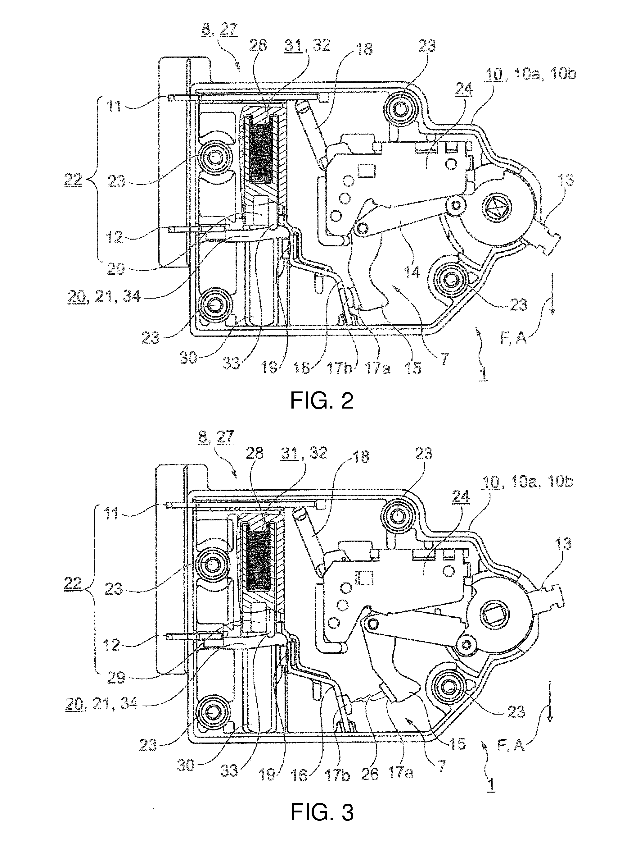
[0053]In a main current path 6 representing the positive terminal, the switchgear unit 1 generally contains two subsystems for DC isolation of the PV generator 2 from the inverter 3. The first subsystem is a manually operable mechanical contact system 7, and the second subsystem is a failsafe system 8 which trips automatically in the event of a fault. In a return line 9, representing the negative terminal, of the switchg...


PUM


Abstract

A switchgear unit switches high DC voltages, particularly for interrupting of direct current between a direct current source and an electrical device. The switchgear unit contains two connections which project from a housing and which are electrically conductively coupled by a conductor path, a contact system which is arranged between the first and second connections and an isolating apparatus that can be tripped by a thermal fuse. The thermal fuse contains a melting location which is arranged in the conductor path and which is connected first to the contact system and second via a moving conductor section to the first connection. The isolating apparatus is tripped and the connection between the conductor section and the contact system is broken at the melting location when an arc produced when the contact system is opened has caused the melting temperature of the melting location to be reached or exceeded.

Description

CROSS-REFERENCE TO RELATED APPLICATION[0001]This application is a continuation application, under 35 U.S.C. §120, of copending international application No. PCT / EP2011 / 005616, filed Nov. 9, 2011, which designated the United States; this application also claims the priority, under 35 U.S.C. §119, of German patent application No. DE 20 2011 001 891, filed Jan. 25, 2011, and German patent application No. DE 10 2011 015 449, filed Mar. 30, 2011; the prior applications are herewith incorporated by reference in their entireties.BACKGROUND OF THE INVENTIONField of the Invention[0002]The invention relates to a switchgear unit for switching high DC voltages, particularly for interrupting direct current between a direct current source and an electrical device. The switchgear unit has two connections which project from a housing and which are electrically conductively coupled by a conductor path, and a mechanical contact system, arranged between the first and second connections. The switchgear...

Claims


Application Information

Patent Timeline
Patent Type & Authority Applications(United States)
IPC IPC(8): H01H85/02
CPCH01H9/32H01H83/10H01H71/122H01H37/761H01H37/76H01H71/12
Inventor WEBER, WALDEMARWERNER, KLAUSHARRER, HUBERTSCHMIDT, WOLFGANG
Owner ELLENBERGER & POENSGEN GMBH
Why Eureka
Try Eureka