Light Source Device and Projection Display Apparatus

a technology of projection display and light source device, which is applied in the direction of static indicating device, lighting and heating device, instruments, etc., can solve the problems of short lifespan and poor reliability, image quality, and speckles that cannot be seen clearly

Active Publication Date: 2012-10-25
PANASONIC CORP
View PDF7 Cites 55 Cited by
  • Summary
  • Abstract
  • Description
  • Claims
  • Application Information

AI Technical Summary

Problems solved by technology

Discharge lamps, however, carry with them problems of short lifespan and poor reliability.
However, with projection display apparatuses using trichromatic red, green and blue laser light sources, there are image quality problems in that speckles stand out, especially in green light.
Further, with light sources using trichromatic red, green and blue LEDs the light emitting efficiency, especially of the green LEDs, is poor, such that improving projection display apparatus brightness has been an issue.
Green light insufficiency is a problem with illumination devices using green LED light sources or green laser light sources, which are poor in light-emitting efficiency.
Therefore, if brightness of the illumination device is to be further enhanced, improving the red light output becomes an issue.
However, while the output power of a blue laser light source and of green fluorescence from excitation using the blue laser light source are relatively easily enhanced, output power of a red LED light source is significantly difficult to improve with there being just a single one.
Therefore, if the output power is increased in a configuration in which blue light is obtained from a laser light source, red light is obtained from an LED, and green light is obtained by exciting a fluorescent material with blue light using the laser-light source employed, the red light will be insufficient.
Consequent problems have been that the balance among red, blue and green necessary for representing white is upset, spoiling the impression of white, or otherwise that when a video image is represented, it turns out to be an image in which the red alone is dark.
However, in conventional projection display apparatuses employing fluorescent materials, light sources of a plurality of colors being independently present means the number of parts is large.

Method used


Image

  • Light Source Device and Projection Display Apparatus
  • Light Source Device and Projection Display Apparatus
  • Light Source Device and Projection Display Apparatus

Examples


first embodiment

Modification of First Embodiment

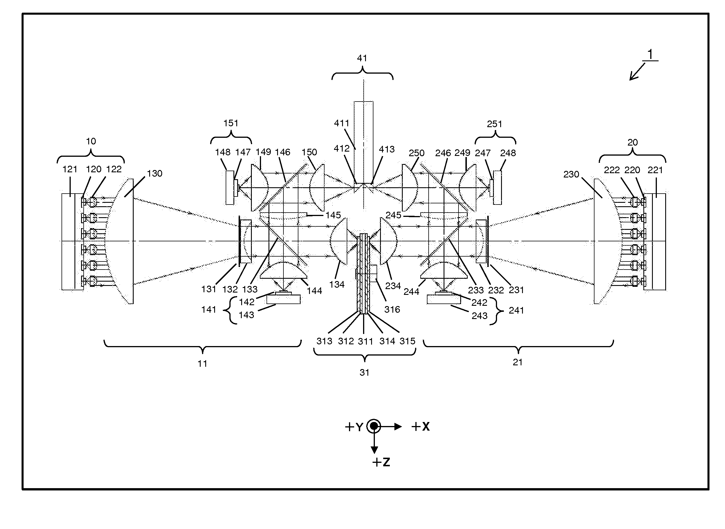
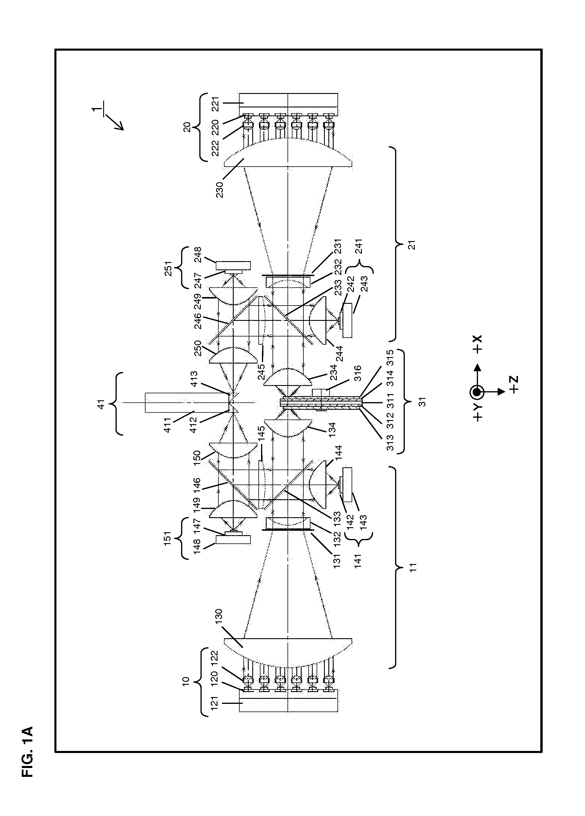
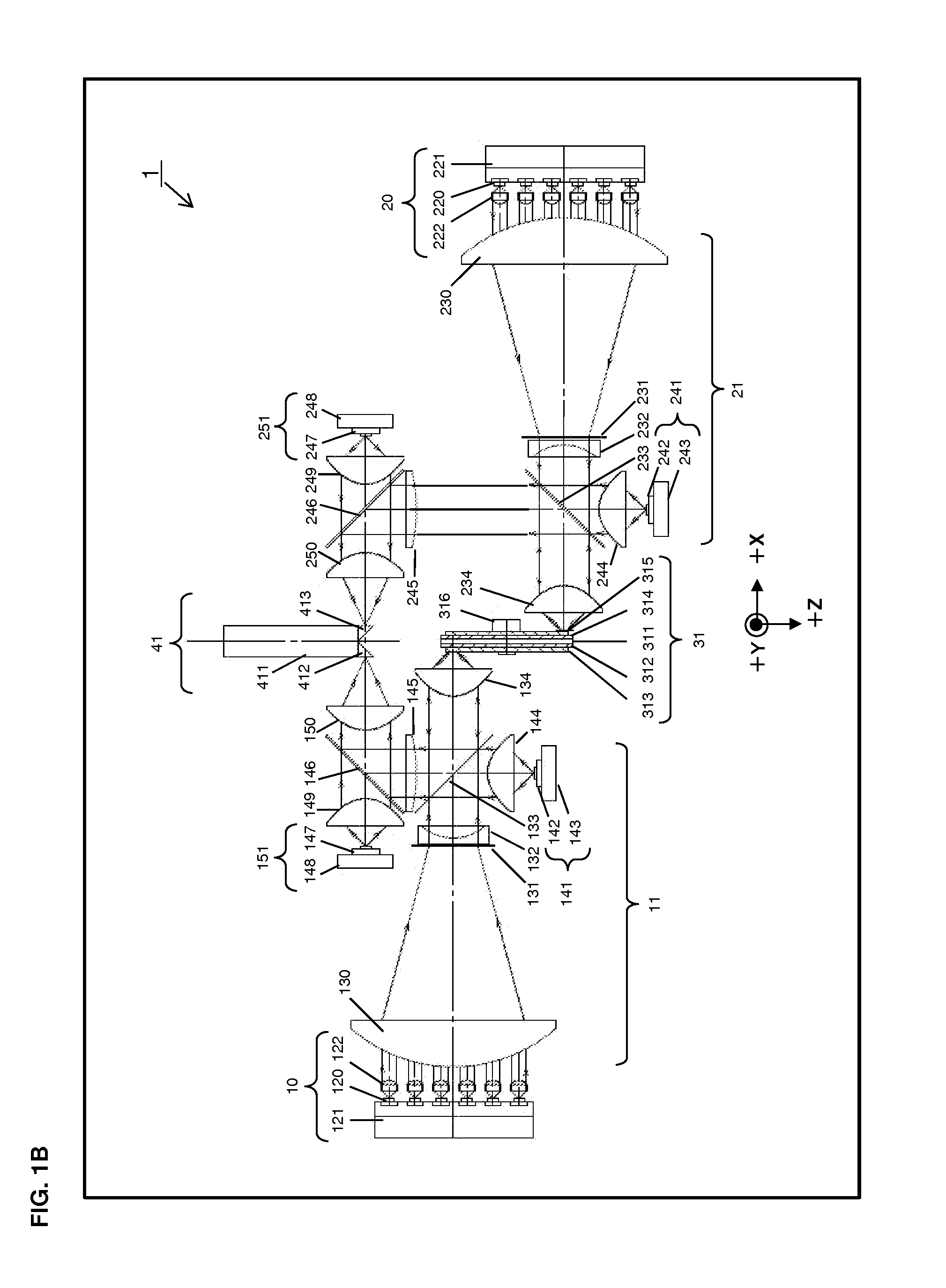
[0082]FIG. 1B illustrates an exemplary modification of the light source device 1 according to the first embodiment. The same components as those shown in FIG. 1A are denoted by the same corresponding reference numerals. The excitation light from the solid-state light source unit 20 is collected by the condenser lens 234, and spot-applied to the second surface on which the fluorescent material layer 315 of the fluorescent plate 31 is formed. However, the modification of the first embodiment is different from the first embodiment in a spot-applied position on the second surface. Specifically, the spot-applied position on the second surface is a position obtained by turning 180 degrees a position at which the excitation light collected by the condenser lens 134 are spot-applied to the first surface on which the fluorescent material layer 313 of the fluorescent plate 31 is formed. The solid-state light source unit 20, the second optical system 21, and the...

second embodiment

[0084]FIG. 3 illustrates a structure of a light source device 2 according to a second embodiment of the present invention. In FIG. 3, (a) represents a front view of the light source device 2, (b) represents a left side view of the light source device 2, and (c) represents a right side view of the light source device 2. The light source device 2, shown in FIG. 3, according to the second embodiment includes the solid-state light source units 10 and 20, a first optical system 12, a second optical system 22, a fluorescent plate 32, and the light combining section 41.

[0085]FIG. 4 illustrates in detail an exemplary structure of the fluorescent plate 32, and (a) represents a front view thereof and (b) represents a side view thereof.

[0086]As shown in FIG. 3, the light source device 2 according to the second embodiment is different from the light source device 1 according to the first embodiment in that the light source device 2 includes the first optical system 12, the second optical system...

third embodiment

[0100]FIG. 5 illustrates a structure of a light source device 3 according to a third embodiment of the present invention. The light source device 3, shown in FIG. 5, according to the third embodiment includes the solid-state light source unit 10, the first optical system 11, a second optical system 23, a fluorescent plate 33, and the light combining section 41.

[0101]FIG. 6 illustrates in detail an exemplary structure of the fluorescent plate 33, and (a) represents a front view thereof and (b) represents a side view thereof.

[0102]As shown in FIG. 5, the light source device 3 of the third embodiment is the same as the light source device 1 of the first embodiment except that the light source device 3 does not include the solid-state light source unit 20, and has the second optical system 23 and the fluorescent plate33 that have structures different from those of the light source device 1. The positioning of components of the light source device 3 is the same as that of the light sourc...


PUM


Abstract

A solid-state light source unit emits excitation light. Fluorescent material layer is formed on each side of a glass substrate of a fluorescent plate so as to interpose a reflective film therebetween. The first optical system optically guides, to a rod integrator, red and blue LED light, and green fluorescence that is generated by excitation occurring when blue laser light emitted from the solid-state light source unit is applied to the fluorescent material layer on one surface of the fluorescent plate, and that is emitted in the −X direction. The second optical system optically guides, to the rod integrator, red and blue LED light, and green fluorescence that is generated by excitation occurring when blue laser light emitted from the solid-state light source unit is applied to the fluorescent material layer on the other surface of the fluorescent plate, and that is emitted in the +X direction.

Description

BACKGROUND OF THE INVENTION[0001]1. Field of the Invention[0002]The present invention relates to projection display apparatuses that with illumination light illuminate images formed on light valves and that by means of projection lenses enlarge and project the images on a screen, and relates to light source devices used in such projection display apparatuses.[0003]2. Description of the Background Art[0004]Discharge lamps are widely employed as light sources for projection display apparatuses using liquid-crystal or minor-deflection type digital micromirror devices (DMDs) for light valves. Discharge lamps, however, carry with them problems of short lifespan and poor reliability.[0005]In order to solve these problems, projection display apparatuses that use, as the light sources, solid-state light sources such as semiconductor lasers or light emitting diodes (LEDs) have been suggested.[0006]However, with projection display apparatuses using trichromatic red, green and blue laser light...

Claims


Application Information

Patent Timeline
Patent Type & Authority Applications(United States)
IPC IPC(8): G09G5/00F21V9/16
CPCH04N9/3161G03B21/204G03B21/2013H04N9/3164
Inventor SUGIYAMA, HIROKIKITANO, HIROSHI
Owner PANASONIC CORP
Why Eureka
Try Eureka