Imager integrated circuit and stereoscopic image capture device

a stereoscopic image and integrated circuit technology, applied in the field of fixed or moving stereoscopic image capture, can solve the problems of stereoscopy loss, stereoscopic images generally suffer from these approximations, and the constraints of the optical system are in this case very strong

Inactive Publication Date: 2012-10-25
COMMISSARIAT A LENERGIE ATOMIQUE ET AUX ENERGIES ALTERNATIVES
View PDF10 Cites 129 Cited by
  • Summary
  • Abstract
  • Description
  • Claims
  • Application Information

AI Technical Summary

Problems solved by technology

Approximations are necessarily performed on these constraints, consequently the resulting stereoscopic images generally suffer from these approximations.
This non-simultaneity of the captured images however gives rise to a problem when an element of this scene is rapidly moving because in this case, the stereoscopy is lost, since the object is in two different positions on the right and left images...

Method used


Image

  • Imager integrated circuit and stereoscopic image capture device
  • Imager integrated circuit and stereoscopic image capture device
  • Imager integrated circuit and stereoscopic image capture device

Examples


first embodiment

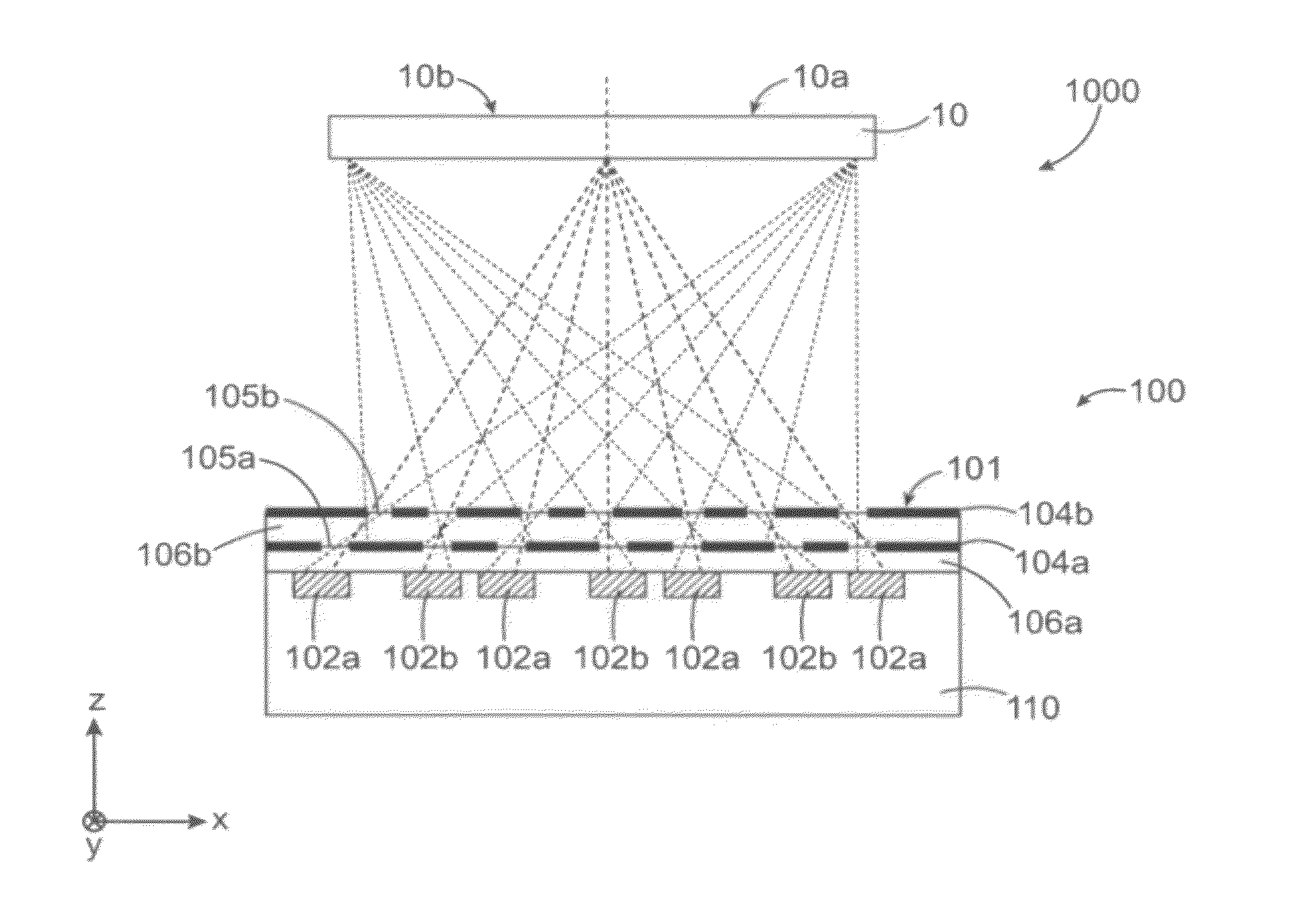
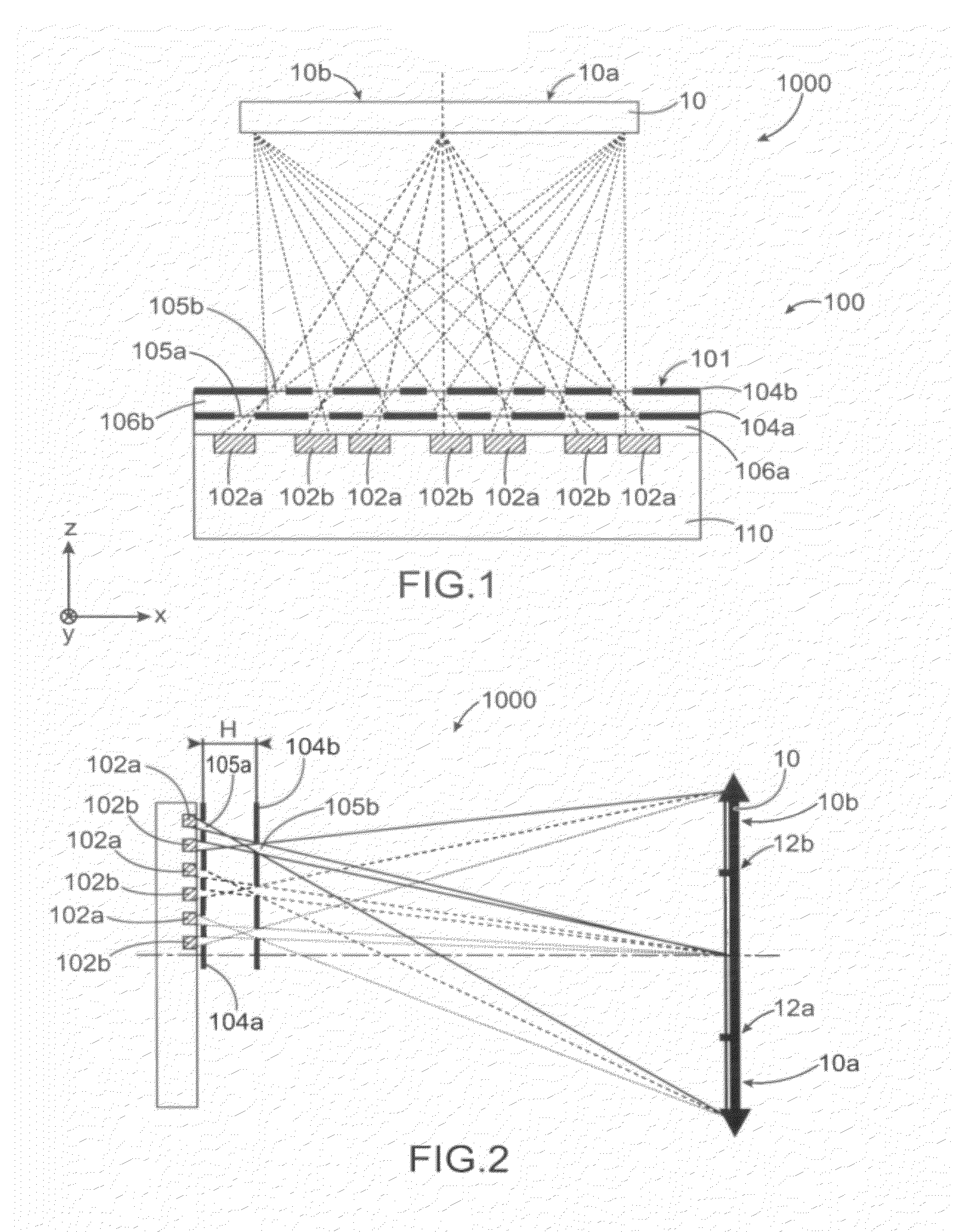
[0037]In a first embodiment, said means may include at least two opaque layers superimposed above each other, provided between the pixels and the inlet face of the imager integrated circuit, both opaque layers having, passing therethrough, a plurality of holes forming, towards each pixel, at least one pair of superimposed diaphragms capable of passing a part of the light rays corresponding to the image associated with the subset of pixels of which said pixel is part and which are capable of blocking other light rays directed from the optical system to said pixels and corresponding to the other images.

[0038]In a first alternative, the number of holes passing through each of both opaque layers may be equal to the total number of pixels of the N subsets of pixels.

[0039]When N=2 and said portion of the optical system corresponds to half the optical system (that is m=2), a distance H between the pixels and a second one of both opaque layers, a first one of both opaque layers being provid...

second embodiment

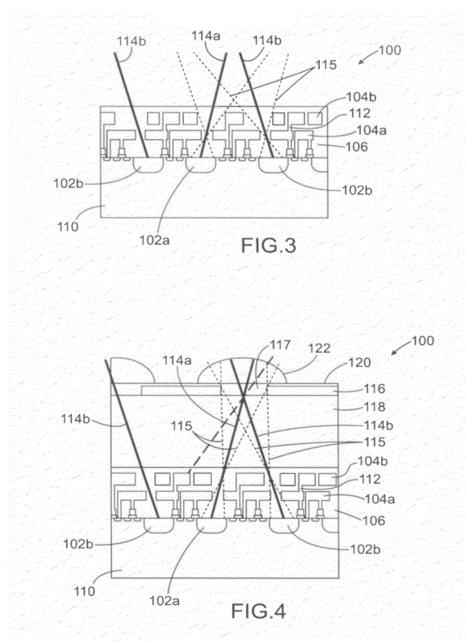
[0057]In a second embodiment, said means may include at least two levels of colour filters superimposed above each other, provided between the pixels and the inlet face of the imager integrated circuit, and may form, towards each pixel, at least one first pair of superimposed colour filters configured to pass part of the light rays corresponding to the image associated with the subset of pixels of which said pixel is part and at least one second pair of superimposed colour filters configured to block the other light rays directed from the optical system to said pixel and corresponding to the other images. This embodiment advantageously uses the colour filters present in a colour image sensor to make the means for capturing stereoscopic images, in particular for “back-side” image sensors wherein the light rays do not pass through the metal interconnection lines of the sensor. Once again, no further shuttering element which would reduce the quantity of light captured by the imager int...


PUM


Abstract

An imager integrated circuit intended to cooperate with an optical system configured to direct light rays from a scene to an inlet face of the circuit, the circuit being configured to perform a simultaneous stereoscopic capture of N images corresponding to N distinct views of the scene, each of the N images corresponding to light rays directed by a portion of the optical system which is different from those directing the rays corresponding to the N-1 other images, including:
    • N subsets of pixels made on a same substrate, each of the N subsets of pixels being intended to perform the capture of one of the N associated images,
    • means interposed between each of the N subsets of pixels and the inlet face of the circuit, and configured to pass the rays corresponding to the image associated with said subset of pixels and block the other rays.

Description

TECHNICAL FIELD[0001]The invention relates to the field of fixed or moving stereoscopic image capture, with at least two views.[0002]The invention is in particular applicable to the fields of endoscopy, microscopy, photography, video cameras (cinema, industrial control, . . . ).STATE OF PRIOR ART[0003]In the fields of photography and video, the stereoscopy, that is a reproduction of a moving or fixed image, in relief from at least two conventional images, that is “planar”, without relief, is generally performed by two (or more) image capture devices, such as cameras or video cameras, directed towards the same scene and enabling images to be captured in this same scene at different points of view.[0004]Several constraints should be met by these devices:[0005]the images of a same scene which are captured at different points of view should be captured simultaneously;[0006]the capture devices should be identical, within the technological dispersion;[0007]the stereoscopic base should be ...

Claims


Application Information

Patent Timeline
IPC IPC(8): H04N13/02G02B30/32
CPCH01L27/14625H04N13/0214H04N13/0282H04N13/0225H04N13/0217H01L27/14627H04N13/211H04N13/214H04N13/218H04N13/225H04N13/282H01L27/14621G02B30/32H04N23/55H04N25/134G01J5/20H04N7/18G02B6/06H04N3/155G02B30/27H04N23/16
Inventor GIDON, PIERRE
Owner COMMISSARIAT A LENERGIE ATOMIQUE ET AUX ENERGIES ALTERNATIVES
Why Eureka
Try Eureka