Optical device, method for manufacturing the same, and projector apparatus including the same

a technology of optical devices and projectors, which is applied in the field of optical devices, can solve the problems of difficult manufacture of prism units, high coating costs, and difficult clamping and aligning of prisms, and achieve the effects of convenient manufacturing, convenient alignment and fastening, and guaranteed quality of optical devices

Inactive Publication Date: 2012-10-25
LITE ON ELECTRONICS (GUANGZHOU) LTD +1
View PDF4 Cites 13 Cited by
  • Summary
  • Abstract
  • Description
  • Claims
  • Application Information

AI Technical Summary

Benefits of technology

[0022]The effect of the present invention resides in that a total internal reflection function is implemented through the substrate. A large area coating process may be performed on the substrates that are laid flat so as to apply the anti-reflection coatings thereon. In this way, variance of coating layers of the optical devices is reduced such that quality of the optical device may be ensured. Moreover, by disposing each of the prisms adjacent to the planar second surface of the corresponding substrate, the prisms may be aligned and fastened with relative ease, so as to achieve effects of easy manufacturing and cost reduction.

Problems solved by technology

In general, since the prisms 11, unlike cuboids or plate-shaped articles, are substantially irregular in shape, it is difficult to clamp and align the prisms 11 when bonding the prisms 11 together, such that manufacture of the prism unit 1 is not easy.
Therefore, the coating process may not be performed on a large number of the prisms 11 at a time, such that a higher coating cost is incurred, and quality variance of the prisms 11 may not be precisely controlled.

Method used


Image

  • Optical device, method for manufacturing the same, and projector apparatus including the same
  • Optical device, method for manufacturing the same, and projector apparatus including the same
  • Optical device, method for manufacturing the same, and projector apparatus including the same

Examples


Embodiment Construction

[0036]Before the present invention is described in greater detail, it should be noted that like elements are denoted by the same reference numerals throughout the disclosure.

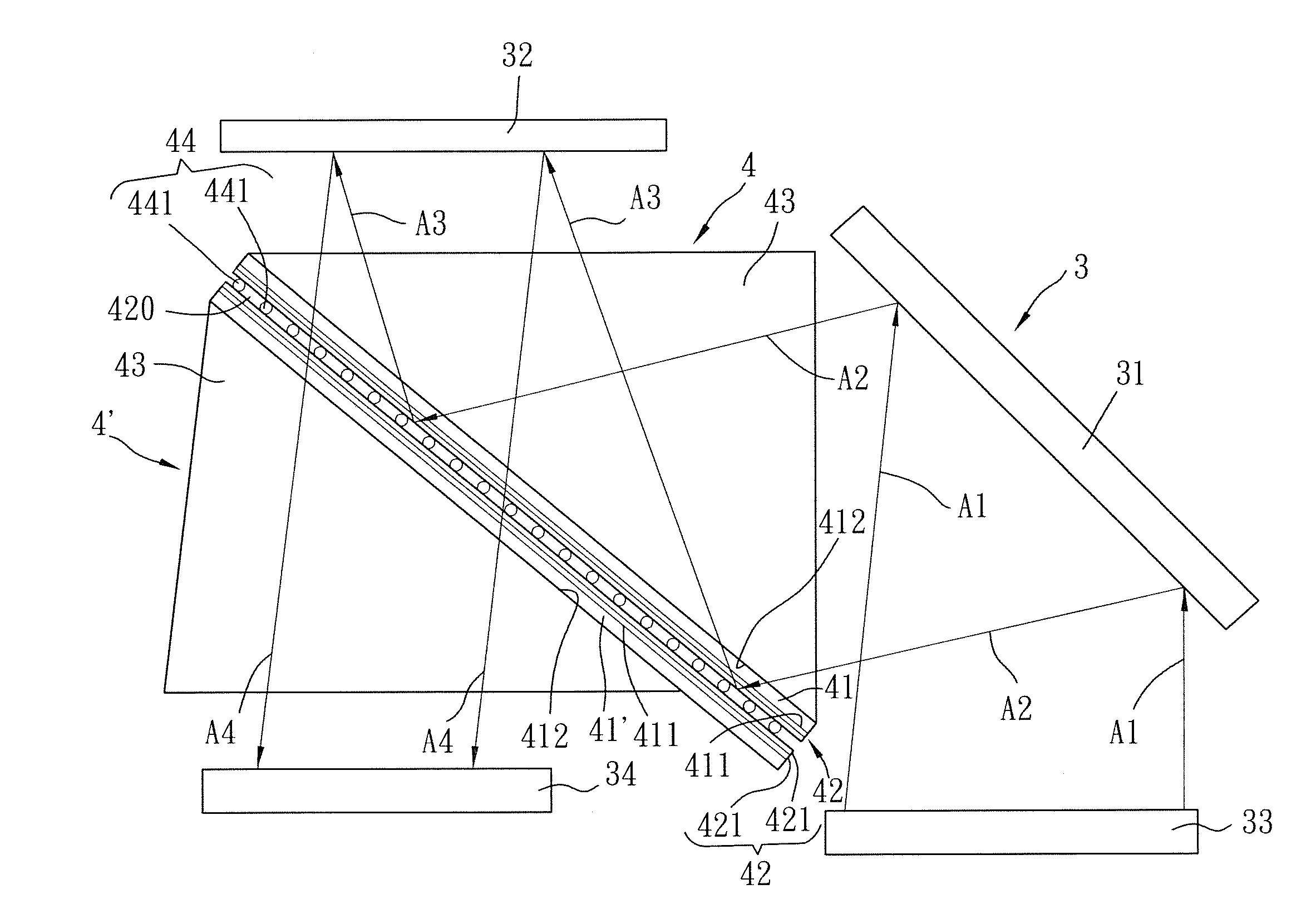
[0037]Referring to FIG. 3, a first preferred embodiment of the optical device, according to the present invention, is applicable to a projector apparatus 3. The projector apparatus 3 includes, aside from the optical device, a light source 33, a reflecting unit 31, a digital micromirror device (DMD) 32, and a projector lens 34. Naturally the projector apparatus further comprises optical filters and other components. Since the feature of the present invention does not reside in the detailed configuration of the optical filters and other components, further details of the same are omitted herein for the sake of brevity.

[0038]The optical device, according to the present invention, comprises a first prism unit 4, a second prism unit 4′ corresponding to and spaced apart from the first prism unit 4, and a spacer unit 4...


PUM

PropertyMeasurementUnit
distanceaaaaaaaaaa
diameteraaaaaaaaaa
diametersaaaaaaaaaa

Abstract

An optical device includes a first prism unit, a second prism unit spaced apart from the first prism unit, and a spacer unit disposed between the first and second prism units. Each of the first and second prism units includes a substrate, an anti-reflection coating, and a prism. The substrate has a first surface disposed to face the other one of the first and second prism units, and a second surface opposite to the first surface. The anti-reflection coating is disposed on the first surface of the substrate. The prism is disposed adjacent to the second surface of the substrate. The spacer unit is disposed between the anti-reflection coatings of the first and second prism units.

Description

CROSS-REFERENCE TO RELATED APPLICATION [0001]This application claims priority of Chinese Application No. 201110109125.4, filed on Apr. 25, 2011.BACKGROUND OF THE INVENTION [0002]1. Field of the Invention[0003]The present invention relates to an optical device, more particularly to an optical device used for reflecting light beams and adjusting optical path, a method for manufacturing the optical device, and a projector apparatus including the optical device.[0004]2. Description of the Related Art[0005]For a current projector apparatus, an illuminating light source should be separated from a projecting light source in the projector apparatus so as to obtain a sharper projected image. A prism unit has been widely applied in the projector apparatus for separating optical paths of the illuminating light source and the projecting light source. Referring to FIG. 1, a conventional prism unit 1 of a projector apparatus 2 is illustrated. The prism unit 1 includes two prisms 11 each having a ...

Claims


Application Information

Patent Timeline
Patent Type & Authority Applications(United States)
IPC IPC(8): G03B21/28C23F1/02B32B37/06G02B5/04B32B37/12
CPCG02B5/04G03B21/008Y10T156/10G03B21/28G03B21/2066
Inventor WANG, CHIEH-WENPENG, WEI-JIELEE, WEI-HWA
Owner LITE ON ELECTRONICS (GUANGZHOU) LTD
Why Eureka
Try Eureka