
Grooving insert and method for producing a grooving insert

a technology of inserts and grooving, which is applied in the direction of cutting inserts, shaping cutters, manufacturing tools, etc., can solve the problems of grooving inserts, further problems, and more difficult to provide optimum retention, and achieve the effect of convenient fastening and high efficiency

Active Publication Date: 2012-10-25
KENNAMETAL INC
View PDF5 Cites 28 Cited by
  • Summary
  • Abstract
  • Description
  • Claims
  • Application Information

AI Technical Summary

Benefits of technology

[0007]The object of the invention is to provide a grooving insert, in particular a tangential grooving insert, which can be readily fastened in the tool holder and is distinguished by a high efficiency.
[0011]In previous indexable cutting inserts in which the cutting edges adjoin opposite ends and the top side, there is the problem that the grooving insert, although it first tapers toward the tool holder, then becomes wider again, since the second side lying opposite has the same width as the first. The grooving depth is therefore limited by the length of the grooving insert. These disadvantages are avoided by the invention. Furthermore, the cube shape is compact, material-saving and permits fastening to the holder while avoiding long lever arms or projecting retaining lugs, which are difficult to produce and do not allow indexing of the grooving insert at all.
[0019]The invention also relates to a tool comprising a tool holder and a grooving insert according to the invention, wherein the tool is a deep-recessing tool, a cutting-off tool or a side milling cutter. The tool according to the invention is distinguished by extreme cutting depths, and still with excellent retention of the grooving insert on the tool holder.
[0025]The bearing surface and the mating surfaces do not need to intersect one another; it is advantageous if a continuous groove is provided in the tool holder in the imaginary intersecting region.
[0026]A method according to the invention for producing a grooving insert according to the invention, in particular a tangential grooving insert, provides for the grooving insert to be produced by a pressing technique, in particular by sintering, to be precise in two or more compression directions. These different compression directions are advantageous for producing the relatively complex prismatic supporting side and / or the plurality of cutting edges.

Problems solved by technology

Such grooving inserts have a width which is greater than that of the very narrow tool holder, and therefore it is more difficult to provide optimum retention in the case of grooving inserts.
Large grooving depths (over 30 mm) in particular cause further problems.
The leverages which arise during the clamping of the grooving inserts become increasingly unfavorable at large grooving depths.

Method used


Image

  • Grooving insert and method for producing a grooving insert
  • Grooving insert and method for producing a grooving insert
  • Grooving insert and method for producing a grooving insert

Examples


Embodiment Construction

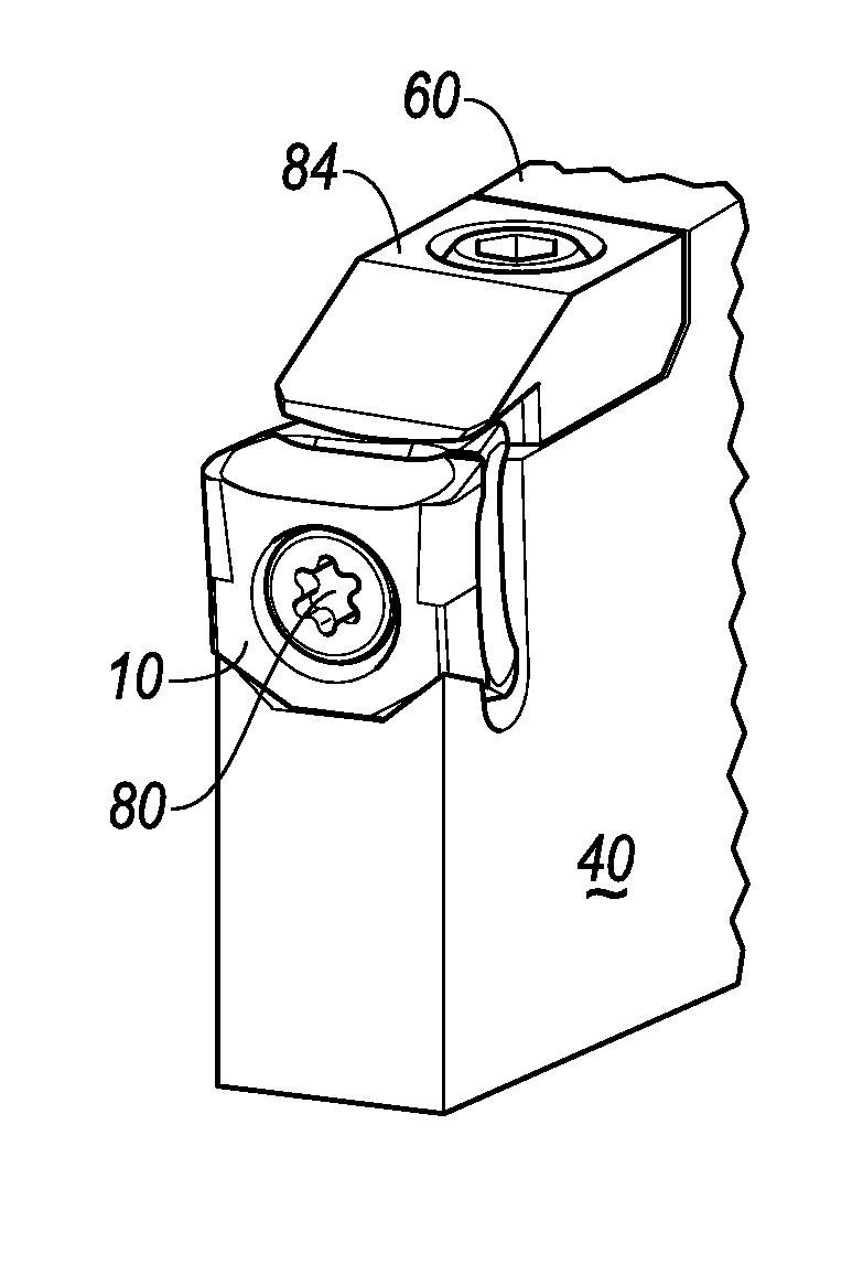
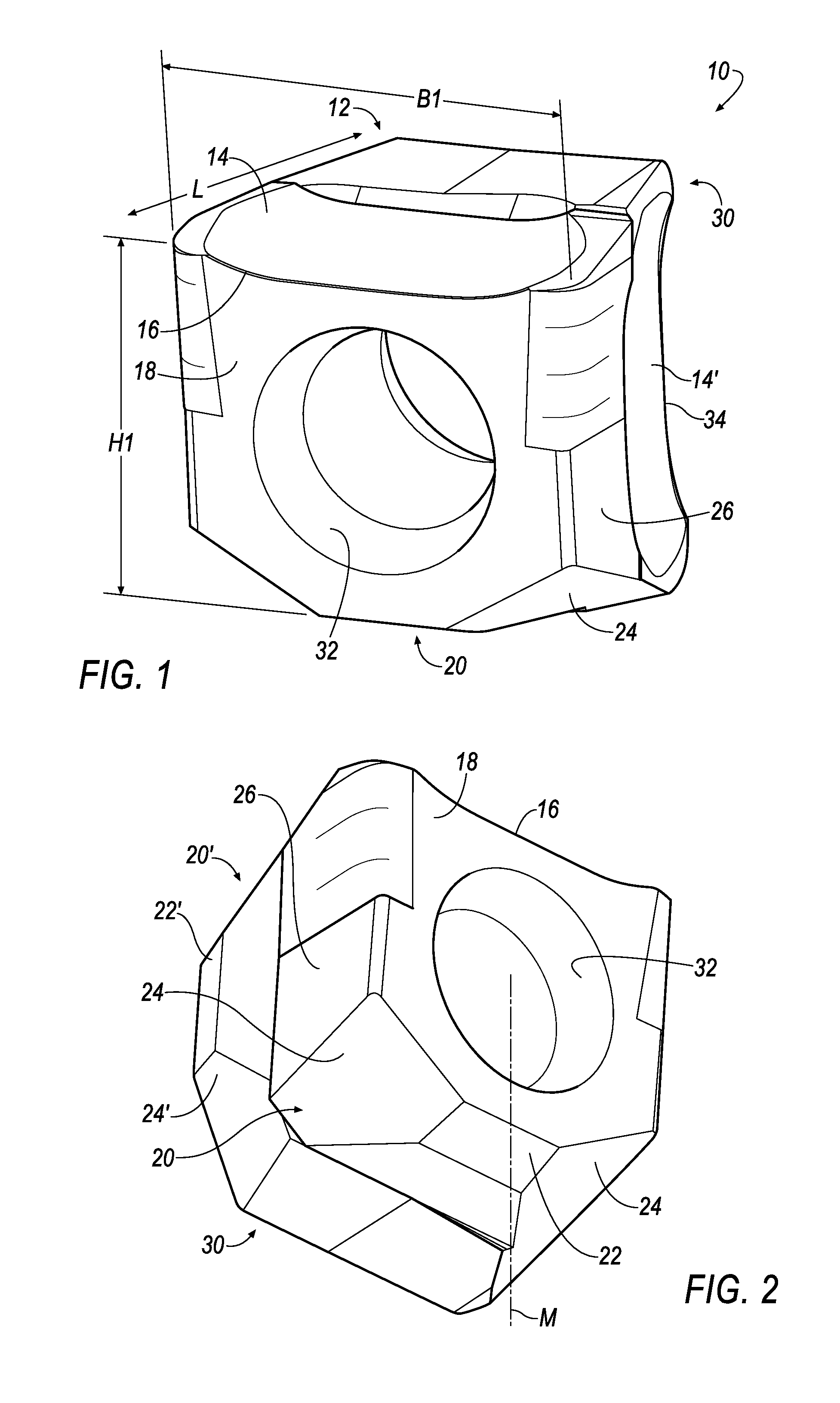
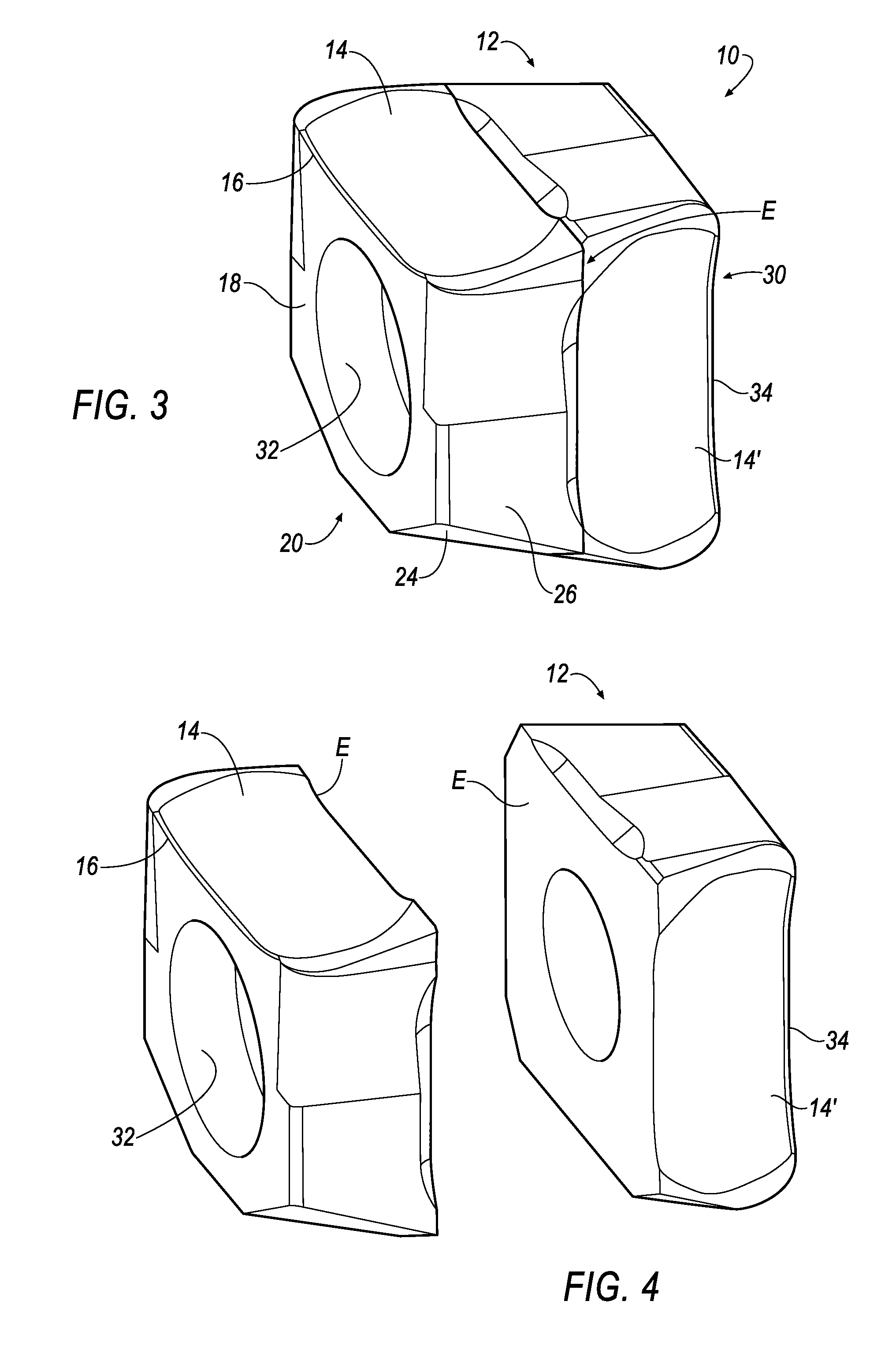
[0042]Shown in FIG. 1 is a tangential grooving insert 10 which has a top side 12 with a rake face 14 in the form of a flute and a cutting edge 16 extending over the entire width B1 of the grooving insert 10.

[0043]The flank 14 and the front main flank 18 meet one another at the cutting edge 16.

[0044]The grooving insert 10 has a length L which is less than the height H1 and the width B1. The overall configuration of the grooving insert 10 is substantially cube-shaped.

[0045]On the underside, referred to below as supporting side 20, which is opposite the top side 12, the grooving insert 10 is of prismatic design, as can better be seen in FIG. 2.

[0046]In the exemplary embodiment shown, the supporting side 20, at least at its margin toward the flank 18, is designed to bulge convexly downward toward the center roughly over half of its length in the direction L.

[0047]The center is preferably formed by a flat surface 22, along which the grooving insert 10 has its maximum height H1.

[0048]The ...


PUM

PropertyMeasurementUnit
angleaaaaaaaaaa
angleaaaaaaaaaa
angleaaaaaaaaaa

Abstract

A grooving insert comprising a cutting edge (16) extending over the width (B) of the insert (10), a main flank (18) and a rake face (14) and also a supporting side (20) opposite the rake face (14) is characterized in that the grooving insert has a substantially cube-shaped outer contour and consists of two geometrically identical cube halves merging into one another in a parting plane, wherein each cube half has a separate cutting edge and the cube halves lie so as to be rotated by 90° relative to one another and turned by 180° relative to one another.

Description

BACKGROUND OF THE INVENTION[0001]1. Field of the Invention[0002]The invention relates to a grooving insert, in particular a tangential grooving insert, comprising a cutting edge extending over the width of the grooving insert, a flank and a rake face and also a supporting side opposite the rake face.[0003]2. Description of Related Art[0004]Grooving inserts are used as interchangeable cutting inserts in deep-recessing or cutting-off tools and in side milling cutters. With such grooving inserts, for example turned workpieces are cut off or bars and tubes are cut to length. Such grooving inserts have a width which is greater than that of the very narrow tool holder, and therefore it is more difficult to provide optimum retention in the case of grooving inserts. Large grooving depths (over 30 mm) in particular cause further problems. The leverages which arise during the clamping of the grooving inserts become increasingly unfavorable at large grooving depths.[0005]By definition, paralle...

Claims


Application Information

Patent Timeline
Patent Type & Authority Applications(United States)
IPC IPC(8): B23B27/16B30B13/00B23P15/28B23B27/22B23C5/20
CPCB22F2005/001Y10T407/2272B23B27/1622B23B27/164B23B27/1651B23B29/043B23B2200/0423B23B2200/0471B23B2200/3681B23B2200/369B23B2205/12B23C5/08B23C5/2221B23C5/2247B23C2200/0416B23C2200/0455B23C2200/367B22F5/10Y10T407/235Y10T407/1934Y10T407/23Y10T407/2268B23B27/04B23C5/2213
Inventor KAUFMANN, IGOR
Owner KENNAMETAL INC
Features
  • Generate Ideas
  • Intellectual Property
  • Life Sciences
  • Materials
  • Tech Scout
  • Unparalleled Data Quality
  • Higher Quality Content
  • 60% Fewer Hallucinations
Learn More