Particulate material production method and apparatus, toner production method and apparatus, and toner

a technology of toner production method and production method, which is applied in the direction of packaging, instruments, developers, etc., can solve the problems of deterioration of production efficiency, increased costs of toner production apparatus, and difficulty in forming uniformly-shaped parts of toner

Active Publication Date: 2012-10-25
RICOH KK
View PDF4 Cites 26 Cited by
  • Summary
  • Abstract
  • Description
  • Claims
  • Application Information

AI Technical Summary

Problems solved by technology

Soap-free polymerization methods have advantages such that a particulate resin having a relatively small particle diameter and a sharp particle diameter distribution can be produced; and the particle form is nearly spherical, but have drawbacks such that a long time, and large amounts of water and energy are necessary for producing a particulate material because it takes time to perform such a polymerization reaction, it takes time to remove a solvent (typically water) from the liquid in which the reaction is performed, resulting in deterioration of production efficiency, and it is necessary to perform various processes such as a process for separating the resultant particulate material, and processes for washing and drying the particulate material after producing the particulate material in the liquid.
Therefore, it is hard to form a uniformly-shaped particulate toner.
Since this toner production method uses two airflow generating devices, the costs of the toner production apparatus increase.

Method used


Image

  • Particulate material production method and apparatus, toner production method and apparatus, and toner
  • Particulate material production method and apparatus, toner production method and apparatus, and toner
  • Particulate material production method and apparatus, toner production method and apparatus, and toner

Examples


example 1

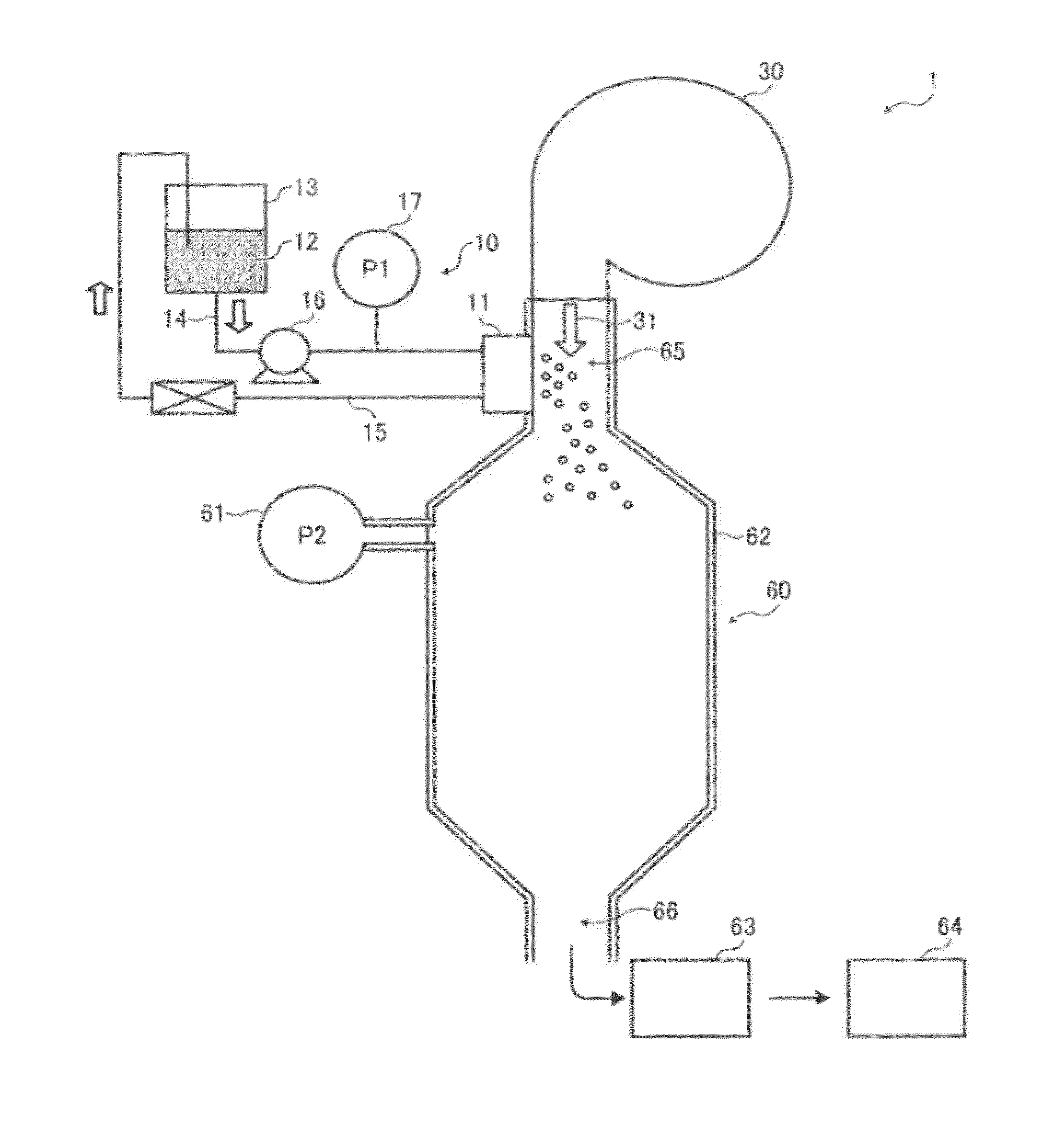
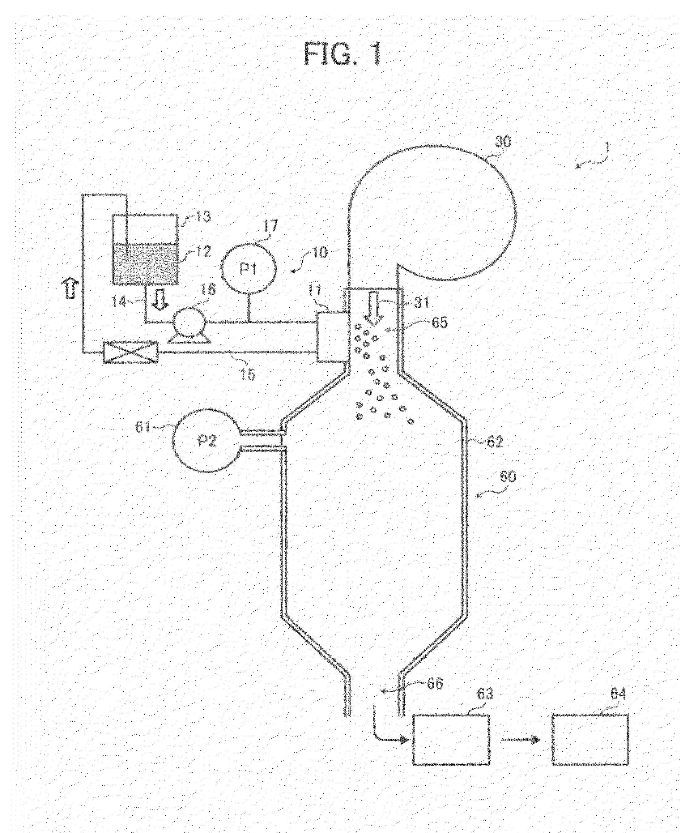
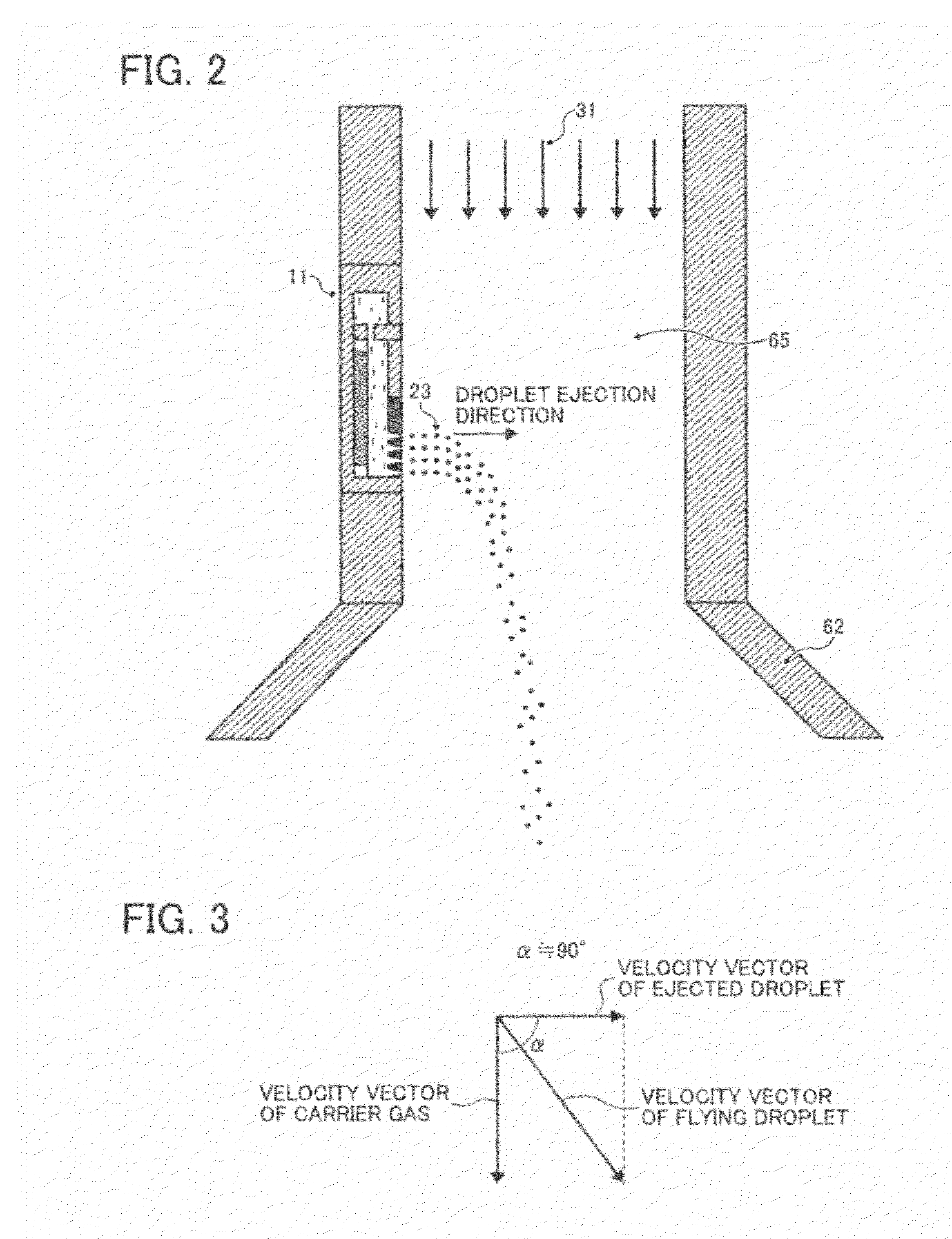
[0173]The above-prepared toner composition liquid was ejected using the above-mentioned toner production apparatus so as to be dried in the chamber 62. Dried particles (i.e., toner particles) in the chamber 62 were collected by the toner collector 63, and then stored in the toner container 64. Thus, a toner of Example 1 was prepared. In this regard, the production conditions were as follows.[0174](1) Applied voltage: A sine-wave voltage having a peak value of 12.0V, and a frequency of 340 kHz was used.[0175](2) Velocity of carrier air: 32 m / s[0176](3) Diameter of droplets: 11.8 μm, which was measured by a laser shadowgraphy method.[0177](4) Ejection velocity: 20 m / s in average, which was measured by a laser shadowgraphy method.

[0178]The volume average particle diameter (Dv) and number average particle diameter (Dn) of the toner of Example 1 were measured with a flow particle image analyzer FPIA-3000 from Sysmex Corp. As a result, the volume average particle diameter (Dv) and number ...

example 2

[0185]The procedure for preparation of the toner of Example 1 was repeated except that the velocity of the carrier air was changed to 60 m / s. As a result, the particle diameter and the velocity of the ejected droplets were 11.8 μm and 20 m / s, and the volume average particle diameter (Dv), the number average particle diameter (Dn), and the ratio (Dv / Dn) of the toner of Example 2 were 5.6 μm, 5.2 μm, and 1.08, respectively.

example 3

[0186]The procedure for preparation of the toner of Example 1 was repeated except that the velocity of the carrier air was changed to 15 m / s. As a result, the particle diameter and the velocity of the ejected droplets were 11.8 μm and 20 m / s, and the volume average particle diameter (Dv), the number average particle diameter (Dn), and the ratio (Dv / Dn) of the toner of Example 3 were 5.8 μm, 5.3 μm, and 1.09, respectively.


PUM


Abstract

The particulate material production method includes vibrating a particulate material composition liquid in a liquid column resonance chamber having at least one nozzle to form a standing wave in the particulate material composition liquid caused by liquid column resonance, so that droplets of the particulate material composition liquid are ejected in a droplet ejection direction from the nozzle so as to fly in a space in a flight direction; feeding a gas in a direction substantially perpendicular to the droplet ejection direction to change the flight direction of the ejected droplets; and solidifying the droplets in the space to produce a particulate material. The particulate material composition liquid includes at least a solvent and a component of the particulate material dissolved or dispersed in the solvent, and the nozzle is located at a location corresponding to an anitnode of the standing wave.

Description

CROSS-REFERENCE TO RELATED APPLICATIONS[0001]This patent application is based on and claims priority pursuant to 35 U.S.C. §119 to Japanese Patent Application No. 2011-092876 filed on Apr. 19, 2011 in the Japan Patent Office, the entire disclosure of which is hereby incorporated herein by reference.FIELD OF THE INVENTION[0002]The present invention relates to a particulate material production method and a particulate material production apparatus. In addition, the present invention also relates to a toner production method and a toner production apparatus. Further, the present invention relates to a toner.BACKGROUND OF THE INVENTION[0003]Uniformly-shaped particulate resins can be used for various purposes such as electrophotographic toners, spacers for use in liquid crystal panels, colored particles for use in electronic papers, and carriers for medicines. Specific examples of the method for producing such uniformly-shaped particulate resins include methods in which a uniformly-shape...

Claims


Application Information

Patent Timeline
Patent Type & Authority Applications(United States)
IPC IPC(8): G03G9/087B65D47/18
CPCG03G9/0819G03G9/0802
Inventor KATOH, KIYOTADASHITARA, YASUTADAMASUDA, MINORUNORIKANE, YOSHIHIROKENJOH, KENTATAKAHASHI, SATOSHI
Owner RICOH KK
Why Eureka
Try Eureka