Hybrid Transponder System For Long-Range Sensing and 3D Localization

a transponder system and long-range sensing technology, applied in the field of hydrocarbon production, can solve the problems of difficult to determine the size and orientation of completed hydraulic fractures, inability to meet the requirements of the system, so as to enhance the optimal performance of the overall system, and avoid adversely affecting the overall dimension

Active Publication Date: 2012-11-01
SAUDI ARABIAN OIL CO
View PDF17 Cites 75 Cited by
  • Summary
  • Abstract
  • Description
  • Claims
  • Application Information

AI Technical Summary

Benefits of technology

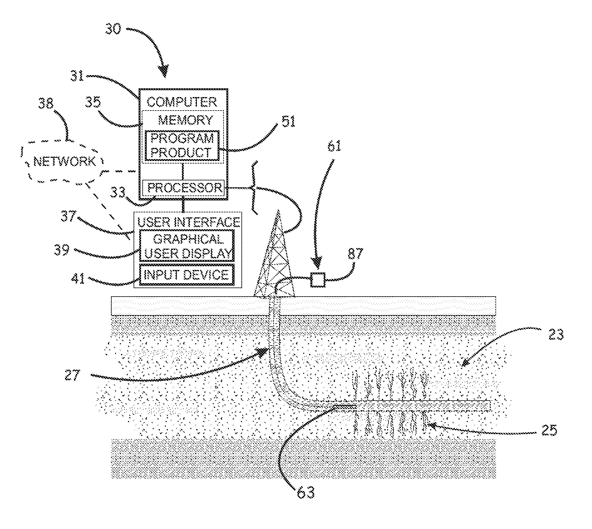
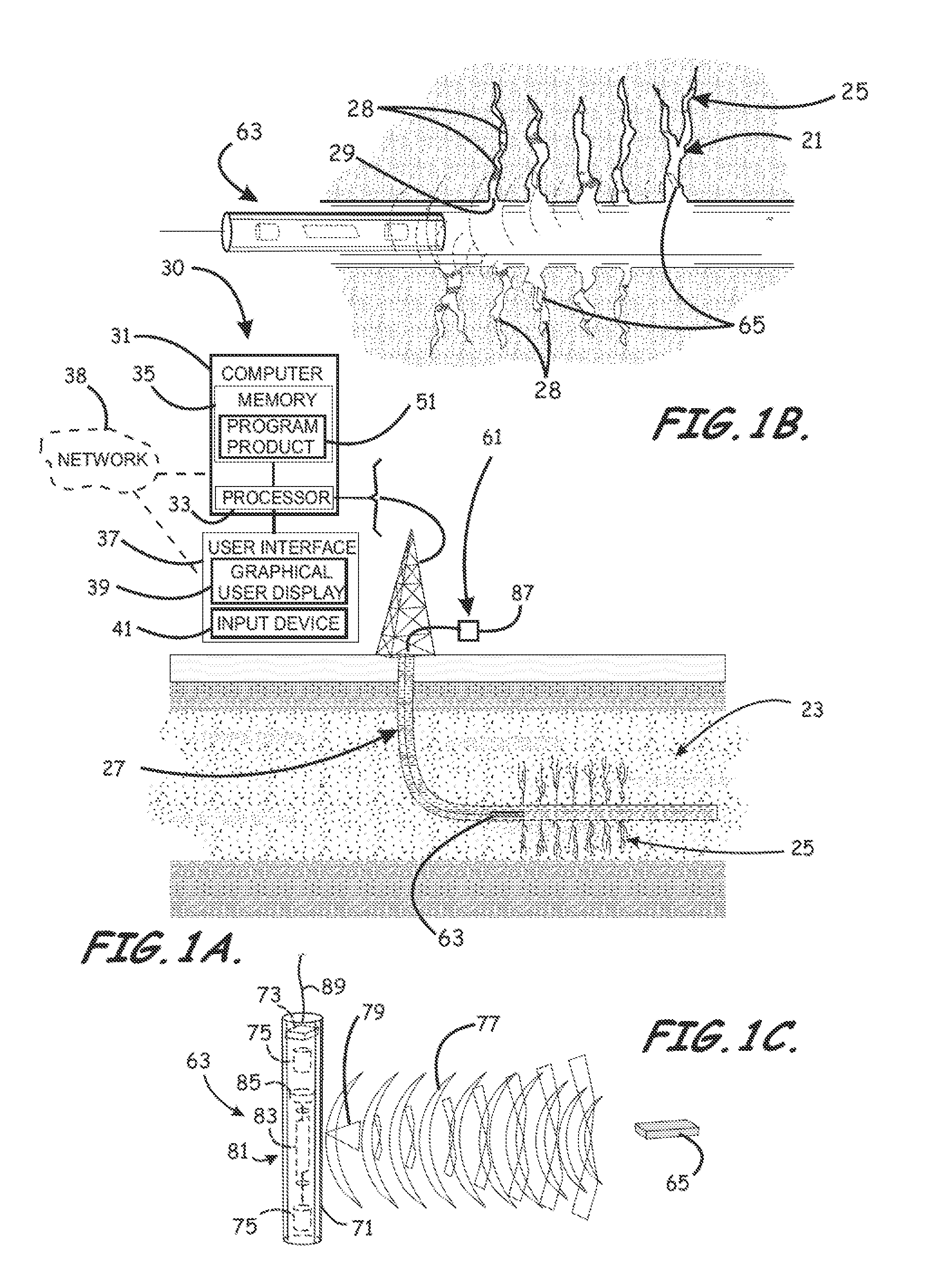
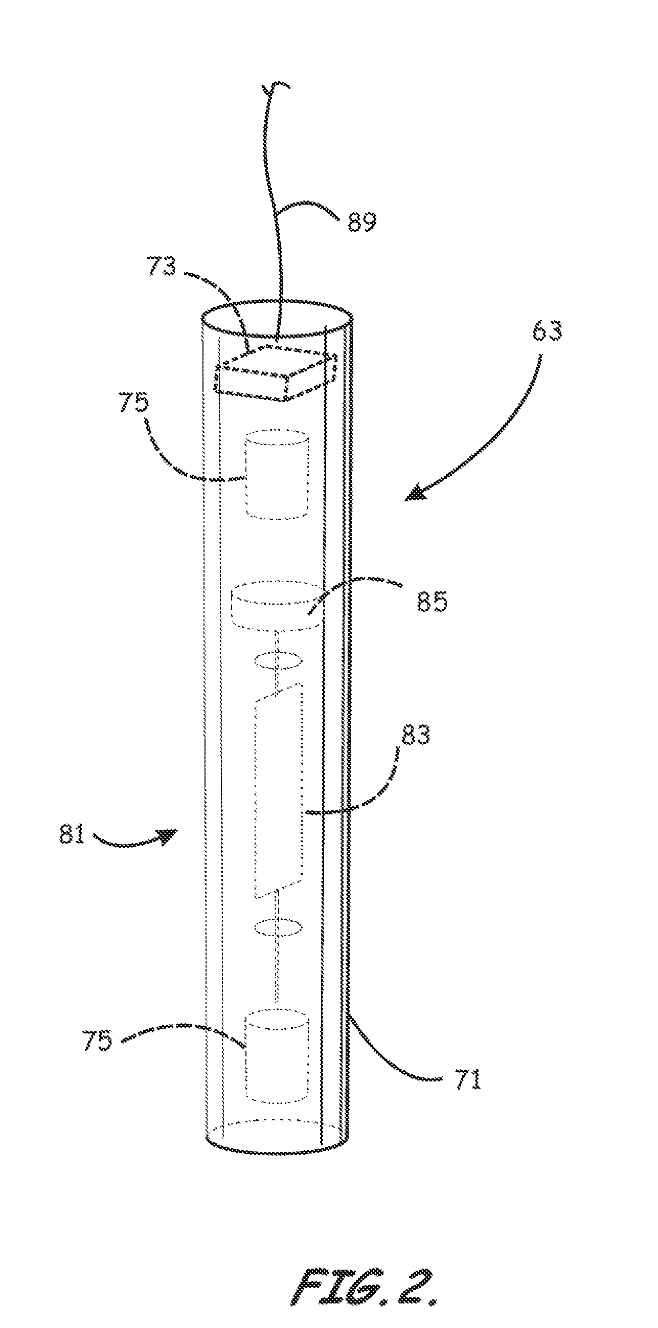
[0014]Each of the transponders typically contain various circuits including a passive radiofrequency identification circuit including an RF antenna, and an acoustic transmitter configured to transmit an acoustic signal such as, for example, and acoustic return signal provided in response to an interrogation and / or control signal from the reader. These “hybrid” transponders, when operationally employed, are disposed in the fracture, having been placed there by being carried along in a fluid injected into the fracture. As such, the dimensions of each transponder are such as allow disposition within the fracture, typically one millimeter or less in one dimension (thickness) and one to ten centimeters or less along the other dimensions (width and length). Each transponder is preferably built up on a flexible electric circuit substrate to allow traversal within the individual fissures. The transponders may optionally be provided with sensor means (external or internal) to measure reservoir parameters in-situ (e.g. salinity, local dielectric constant, temperature, pressure, etc.). The transponders generate an acoustic signal when powered by the RF field and optionally when instructed to do so. The range and position of a transponder relative to a reader may be determined using triangulation to the acoustic signals received by the reader, adjusting the RF power transmitted from the reader or varying the position or orientation of the RF transmitter, or a combination thereof. The transponders are preferably supplied with an RF demodulator and a digital control circuit allowing the receiver to control a given transponder. Example instructions include entering a quiescent state (do not transmit) and transmitting if a measured value is equal to a certain level. Also, optimal performance of this system can be enhanced by the utilization of battery assistance. A thin film battery, for example, may be added to each transponder without adversely affecting its overall dimensions. The assistance of the battery can advantageously enhance optimal performance of the overall system.
[0015]According to an exemplary embodiment of the system, the three dimensional position of a given transponder can be determined from its ability to respond based upon the position and orientation of the reader's RF antenna, as well as the amount of power transmitted, along with the arrival times of its returned acoustic signal at the reader's acoustic receivers. Correspondingly, the reader can be configured so that the power of the reader can be adjusted arbitrarily, and / or the operating frequency of the system can be changed to optimize antenna efficiency and detection range of the transponders. Also, a reflector can be added to the reader antenna to direct the RF energy (and read sensitivity) in one direction, making the response pattern asymmetric.

Problems solved by technology

Determining the size and orientation of completed hydraulic fractures is quite difficult, expensive, and inaccurate.
In general, the read range of typical passive RFID systems is limited to a few meters.
Ideal conditions, however, are seldom the norm.
Also recognized by the inventors is that such arbitrary scaling on the transponder side would not generally be possible for tags that would be required to fit through open hydraulic fractures, and thus, would face significant size limitations, especially in applications where the form factor is especially constrained.

Method used


Image

  • Hybrid Transponder System For Long-Range Sensing and 3D Localization
  • Hybrid Transponder System For Long-Range Sensing and 3D Localization
  • Hybrid Transponder System For Long-Range Sensing and 3D Localization

Examples


Embodiment Construction

[0032]The present invention will now be described more fully hereinafter with reference to the accompanying drawings, which illustrate embodiments of the invention. This invention may, however, be embodied in many different forms and should not be construed as limited to the illustrated embodiments set forth herein. Rather, these embodiments are provided so that this disclosure will be thorough and complete, and will fully convey the scope of the invention to those skilled in the art. Like numbers refer to like elements throughout. Prime notation, if used, indicates similar elements in alternative embodiments.

[0033]Various embodiments of the present invention relate to the use of the principles of radio-frequency identification (RFID) technology to map the shape of hydraulic fractures. The position of one or more transponders can be localized in three dimensions relative to a reader installed in a wellbore. The transponders are carried along in a fluid injected into the hydraulic fr...


PUM


Abstract

Systems for determining a size, extent, and orientation of a hydraulic fracture of a reservoir, are provided. An exemplary system can include a plurality of RFID transponders modified to include an acoustic transmitter, and an RFID reader modified to include both an RF transmitter and a pair of acoustic receivers, to be deployed in a wellbore adjacent a hydraulic fracture. The system includes program product configured to receive acoustic return signal data to determine the three-dimensional location of each RFID transponder within the reservoir, to map the location of each RFID transponder, and to responsively determine the size, extent, and orientation can be determined.

Description

RELATED APPLICATIONS [0001]This application is related to U.S. patent application Ser. No. ______ filed ______ titled “Methods of Employing and Using a Hybrid Transponder System for Long-Range Sensing and 3D Localization,” incorporated by reference in its entirety.BACKGROUND OF THE INVENTION[0002]1. Field of the Invention[0003]The present invention relates in general to the field of hydrocarbon production, and in particular, to methods related to mapping the size and shape of hydraulic fractures in hydrocarbon reservoirs.[0004]2. Description of the Related Art[0005]Hydraulic fractures are frequently employed to improve reservoir contact and production rates in the oil and gas industry. Hydraulic fracturing has been used for over 60 years in more than one million wells. Hydraulic fracture stimulation is commonly applied to wells drilled in low permeability reservoirs. An estimated 90% of the natural gas wells in the United States use hydraulic fracturing to produce gas at economic ra...

Claims


Application Information

Patent Timeline
Patent Type & Authority Applications(United States)
IPC IPC(8): E21B47/00
CPCE21B47/122E21B43/26E21B47/13
Inventor SCHMIDT, HOWARD KHANAL-SHEHRI, ABDULLAH AWADH
Owner SAUDI ARABIAN OIL CO
Why Eureka
Try Eureka