
Visual bilgewater quality indicator

a bilgewater quality indicator and visual technology, applied in the direction of vessel construction, separation process, nature of treatment water, etc., can solve the problems of reducing the detection efficiency of bilgewater, unable to eliminate sheen and remove all harmful contaminants, and unable to meet the requirements of environmental protection and environmental protection. , to achieve the effect of reducing the number of bilgewater discharges, visual enhancement, and easy visual detection

Active Publication Date: 2012-11-01
MYCELX TECH CORP
View PDF3 Cites 0 Cited by
  • Summary
  • Abstract
  • Description
  • Claims
  • Application Information

AI Technical Summary

Benefits of technology

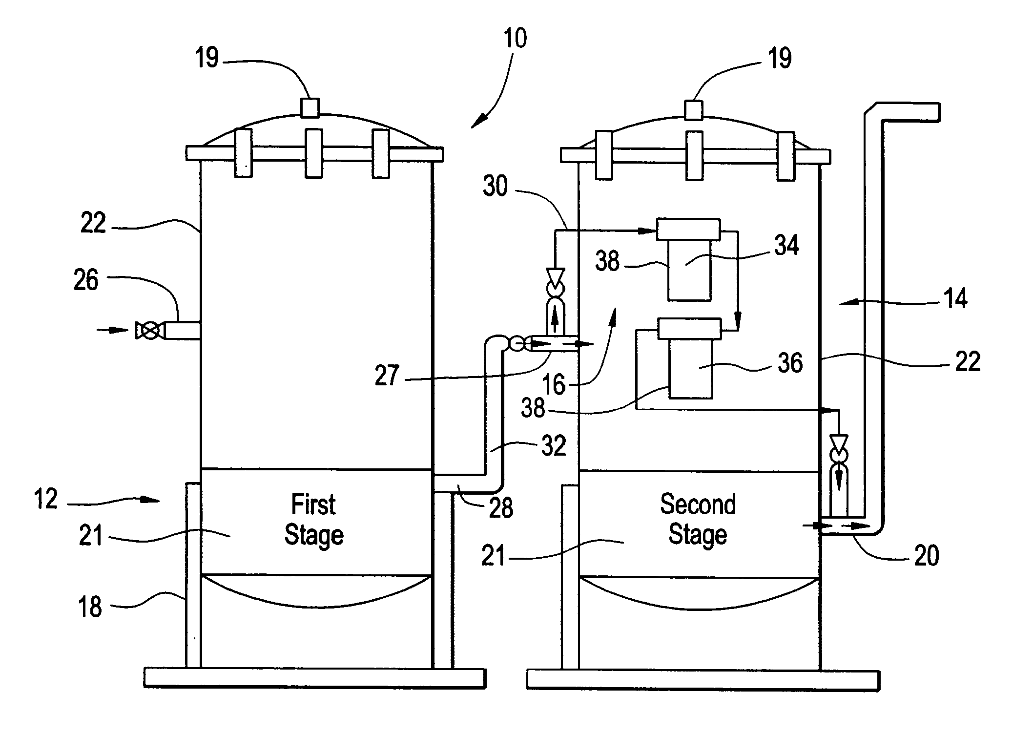
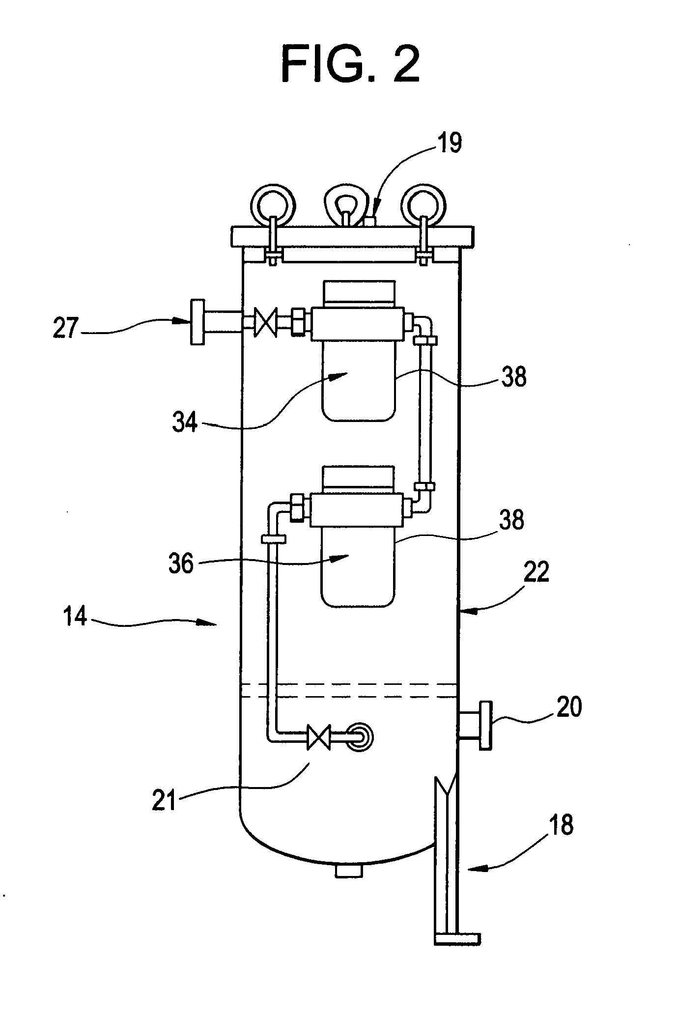
[0021]Now in accordance with the present invention a visual bilge water quality indicator is provided for examining and evaluating the quality of treated effluent flowing in a bilge water filtration system which includes at least a first (i.e. “primary”) filtration stage for removing oily contaminants. The visual indicator can be positioned at any point in the filtration system flow stream where a visual determination is sought regarding the presence and degree of the oily contaminants. Normally (although not necessarily) such examination will be conducted at a point preceding the OCM (oil content monitor) commonly used at the bilge discharge point. The visual indicator preferably is positioned to effect its evaluation at the output line of the said primary filtration stage. A bypass or shunt line is typically connected to divert a test stream from the primary filtration stage output line and return the diverted flow back to the output line of the filtration system. The visual indicator of the invention includes at least a first filtration status chamber connected inline at the bypass line. The status chamber includes a filtration media adapted to absorb said oily contaminants, and a transparent outer wall to enable viewing of the interior of the chamber. The filtration status chamber preferably has means for channeling the flow received therein in a direction which proceeds from the chamber outside wall toward its central axis, whereby oily contaminants in the flow collect selectively at the outermost portions of the filtration media where they are highly visible to an operator or inspector. The filtration media is preferably a fluid-pervious filtration media as referenced in the applicant's above patents, which has thus been infused with an absorbtion composition as also referenced. Furthermore however, the media may include a fluorescent or phosphorescent pigment, whereby the presence of captured oily contaminants is visually enhanced, and can be further augmented by rendering a UV light source incident on the media by passing such radiation through the substantially UV transparent walls of the status chamber. Use of the preferred filtration media just cited is especially significant in that oily droplets are immobilized at the outer surface of the filter, allowing for easy visual detection.

Problems solved by technology

Over the past two decades, U.S. regulations dealing with bilgewater discharge for all types of vessels have grown increasingly stringent.
Environmental technology has struggled to keep pace, but until recently no removal method has been capable of eliminating sheen and extracting all harmful contaminants from bilgewater.
The cumulative effect of vessels ranging from small recreational boats to large surface ships dumping even small amounts of bilgewater could wreak damage upon fragile aquatic ecosystems—and likely has already done so.
In worst-case scenarios, environmentally irresponsible vessel operators have dealt with excess bilgewater by dumping it overboard.
These noxious contaminants are among the more difficult compounds to remove from water, and indeed most are carcinogenic.
The solubility of the foregoing substances renders most prior art physical separation methods ineffective and causes formation of stable and pseudostable oily emulsions (micelle size of 400 micrometers or less), which also don't respond well to gravity separation due to neutral buoyancy.
In the course of utilizing bilgewater filtration systems, including those based upon the foregoing principles, it is often difficult to determine the quality of effluent from oily water separators without relying on sensor readings.
It is often not possible even to determine visually if the unit is on or off.
Inability to perform visual inspection has resulted in accidental oily bilge water discharge and even criminal prosecution.
In the case of oily water treatment devices it is not possible to effectively use transparent sight gauges or glass indicators on the housings or in the connecting piping due to the tendency of the surfaces over which the discharge flows to become opaque from oily fouling.

Method used


Image

  • Visual bilgewater quality indicator
  • Visual bilgewater quality indicator
  • Visual bilgewater quality indicator

Examples


Embodiment Construction

[0031]In a preferred embodiment of the invention illustrated in the drawings, a visual bilgewater quality indicator is provided, which utilizes a by-pass shunt composed of two filtration status chambers in series, each of which are provided with fluorescent or phosphorescent dye treated filtration media. These filters can be of the types discussed in my aforementioned U.S. Pat. No. 6,475,393 patent, wherein the filtration media is also treated with a fluorescent or phosphorescent dye having very high visibility such as a “hot pink” The filters can also be of the types disclosed in the present inventor's copending patent applications Ser. Nos. 11 / 180,301 and 11 / 181,372, filed respectively on Jul. 13,2005 and Jul. 14,2005. Oil droplets as small as one micron, are captured and immobilized by the primary filter and are instantly visible against the hot pink or similar high visibility background of the exemplary dye previously mentioned. Due to the ability of the infused media to permane...


PUM


Abstract

A visual bilgewater quality indicator for use in a bilgewater filtration system which includes a filtration stage for removing oily contaminants. The quality indicator utilizes one or more filtration status chambers which are provided with a fluorescent or phosphorescent dye or pigment treated filtration media. The status chamber has a transparent outer wall. Flow through the status chamber is from the outer lateral wall toward its central axis, whereby oily contaminants in the flow collect selectively at the outer portions of the filtration media which are highly visible to an observer. Oil droplets as small as one micron, are captured and immobilized by the primary filter and are instantly visible against the background of the exemplary dye. If two status chambers are used in series, the second chamber is always kept transparent until complete loading and supersaturating breakthrough at the primary chamber.

Description

RELATED APPLICATION[0001]This application claims priority from U.S. provisional patent application Ser. No. 60 / 920,193, filed on Mar. 27, 2007.FIELD OF INVENTION[0002]This invention relates generally to methods and filtration devices for removing undesired contaminants from bilgewater discharge, and more specifically relates to apparatus for use in a bilgewater filtration system for visually examining the filtered or partially filtered flowing effluent to determine the efficacy and operational state of the filtration system.BACKGROUND OF INVENTION[0003]Over the past two decades, U.S. regulations dealing with bilgewater discharge for all types of vessels have grown increasingly stringent. Even the presence of an oil sheen is punishable under federal law. Environmental technology has struggled to keep pace, but until recently no removal method has been capable of eliminating sheen and extracting all harmful contaminants from bilgewater. Federal regulations set a high standard for bilg...

Claims


Application Information

Patent Timeline
Patent Type & Authority Applications(United States)
IPC IPC(8): B01D35/30
CPCB63J4/002C02F2103/008C02F1/288B63J4/006
Inventor ALPER, HAL
Owner MYCELX TECH CORP
Learn More