Aircraft aerial refuelling system

Active Publication Date: 2012-11-01
AIRBUS OPERATIONS LTD
View PDF2 Cites 7 Cited by
  • Summary
  • Abstract
  • Description
  • Claims
  • Application Information

AI Technical Summary

Benefits of technology

[0017]The fuel pump control system is preferably integrated with the fuel pump and is operable to automatically control the pump outlet fuel pressure depending on the demand fuel pressure signal. The feedback control enables the integrated control system to continuously monitor the pump outlet fuel pressure such that it can instantly react to changing situations without intervention by the aircraft crew.
[0018]For example, in the event of a pipe burst within a fuel tank, the outlet pressure is maintained at the fuel pump demand pressure which is normally set as the safe pressure for a fuel tank. The integrated control system automatically reacts by adjusting the pump power such that the pump outlet pressure does not exceed the demand pressure, thereby ensuring that the tank does not experience a high pressure surge. In this way, the pressure in the fuel pipe never reaches the maximum capability of the pump and so the fuel tank structure can be designed for a lower co

Problems solved by technology

However, simply up-rating the power of existing fuel pump technology presents challenges in the design of other aircraft systems.
An attempt to increase the fuel dispense rate using existing fuel pump technology may necessitate strengthening of the wing structure and/or the overflow system, which could add unacceptable weight to the aircraft.
These step changes in pressure can cause “pipe-hammer” which can contribute to pipe or connector rupture.
An attempt to increase the fuel dispense rate using existing fuel pump technology may exacerbate these step changes in

Method used


Image

  • Aircraft aerial refuelling system
  • Aircraft aerial refuelling system
  • Aircraft aerial refuelling system

Examples


Embodiment Construction

)

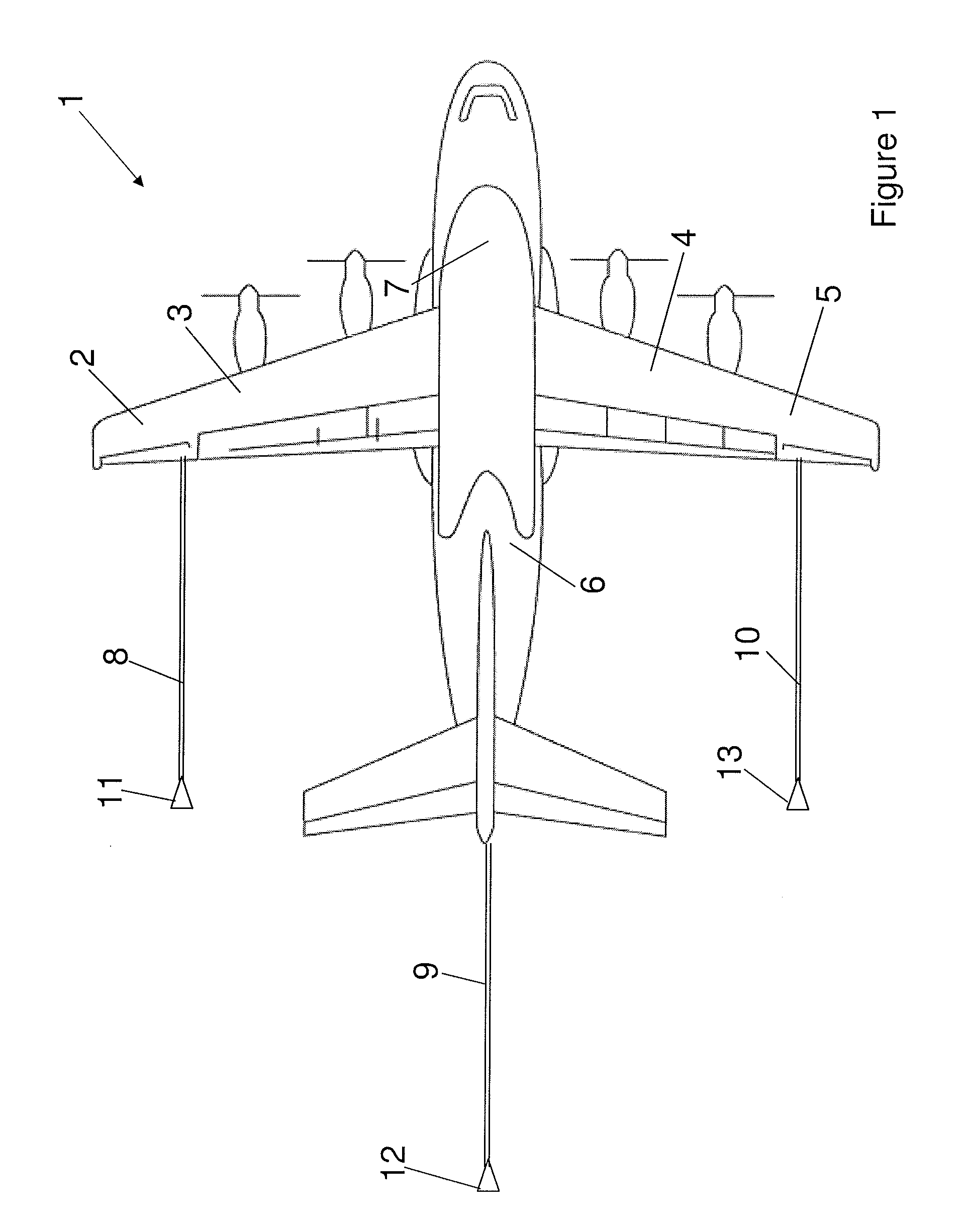
[0040]FIG. 1 illustrates a top plan view of an aerial refueling tanker aircraft 1. The aircraft 1 is equipped with multiple fuel tanks including a left wing tank 3 within left wing 2, a right wing fuel tank 4 within right wing 5, and two auxiliary cargo hold fuel tanks 6, 7, one disposed aft of the wing fuel tanks 3, 4 and another disposed forward of the wing fuel tanks 3, 4 within the aircraft fuselage.

[0041]The aircraft 1 is equipped with multiple fuel dispense stations including one dispense station mounted in under wing pods of both the left and right wings 2, 5 and a further dispense station located in the tail of the aircraft 1. Each dispense station includes a retractable trailing refueling hose 8, 9, 10 having a refueling drogue 11, 12, 13 at its distal end.

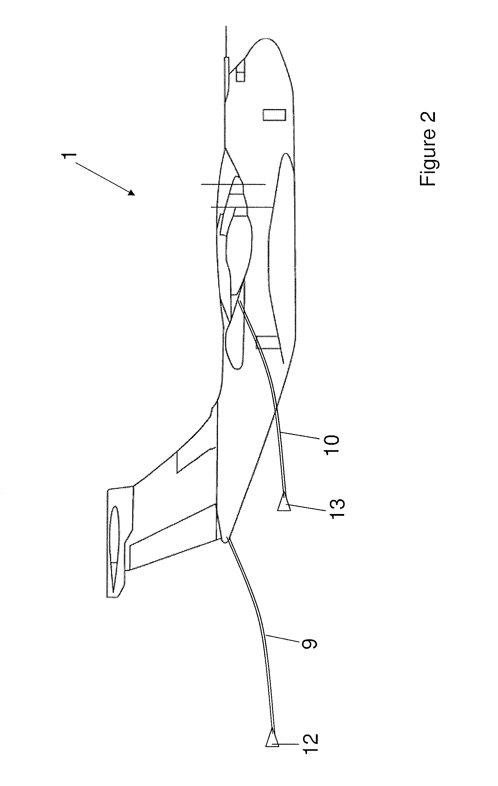
[0042]FIG. 2 illustrates a side view of the aircraft 1 so as to more clearly illustrate the trailing refueling hoses 9, 10. The number and location of the fuel tanks and the number and location of the fuel dispense stati...


PUM


Abstract

An aircraft aerial refueling system including at least one pressure controlled fuel pump having a control system adapted to regulate the pump outlet fuel pressure using an outlet fuel pressure signal as control feedback. Also, methods of operating an aircraft aerial refueling system.

Description

FIELD OF THE INVENTION[0001]The present invention relates to an aircraft aerial refueling system, and in particular relates to a high flow rate dispense fuel pump of the system. The invention also relates to methods of operating the system.BACKGROUND OF THE INVENTION[0002]Aircraft are typically designed to contain fuel in their wings. This fuel is pumped between tanks and to the engines by relatively low power pumps at a rate capable of sustaining the maximum fuel usage of the engines, with a margin of approximately 50%.[0003]Aerial refueling tanker aircraft additionally typically have much more powerful fuel pumps designed to ensure that fuel is dispensed to a receiving aircraft within a reasonably short time. Tanker aircraft typically store fuel in multiple tanks from which fuel can either be used for normal aircraft operation or for refueling following aircraft, e.g. via a trailing hose dispense station. To achieve fast dispense rates it is desirable to pump fuel from several tan...

Claims


Application Information

Patent Timeline
IPC IPC(8): B64D39/00
CPCB64D39/00B64C17/10B64D37/16F04D29/22
Inventor TICHBORNE, FRANKLINLAWSON, MARKFREEMAN, HUGHEPIFANIE, ARNAUDEDWARDS, ADRIAN
Owner AIRBUS OPERATIONS LTD
Why Eureka
Try Eureka