Switched-mode power supply

a power supply and switch-mode technology, applied in the direction of dc-dc conversion, power conversion systems, instruments, etc., can solve the problems of increasing the number of pins, affecting the efficiency of the power supply, and the inability to integrate the ripple injection function into the integrated circuit (ic)

Inactive Publication Date: 2012-11-01
MITSUMI ELECTRIC CO LTD
View PDF3 Cites 33 Cited by
  • Summary
  • Abstract
  • Description
  • Claims
  • Application Information

AI Technical Summary

Benefits of technology

[0012]The present invention was conceived in consideration of the above-described subjects. It is therefore an object of the present invention to integrate the ripple injection function into an IC which serves as the control circuit in a switched-mode power supply based on the ripple control system, without increasing the number of external terminals.

Problems solved by technology

The number of external terminals (number of pins) will therefore increase, and this will push up the cost.
In some cases, it may even be impossible to integrate the ripple injection function into an integrated circuit (IC), due to limitation on the number of external terminals.

Method used


Image

  • Switched-mode power supply
  • Switched-mode power supply
  • Switched-mode power supply

Examples


Embodiment Construction

[0026]Preferred embodiments of the present invention will be explained below, referring to the attached drawings.

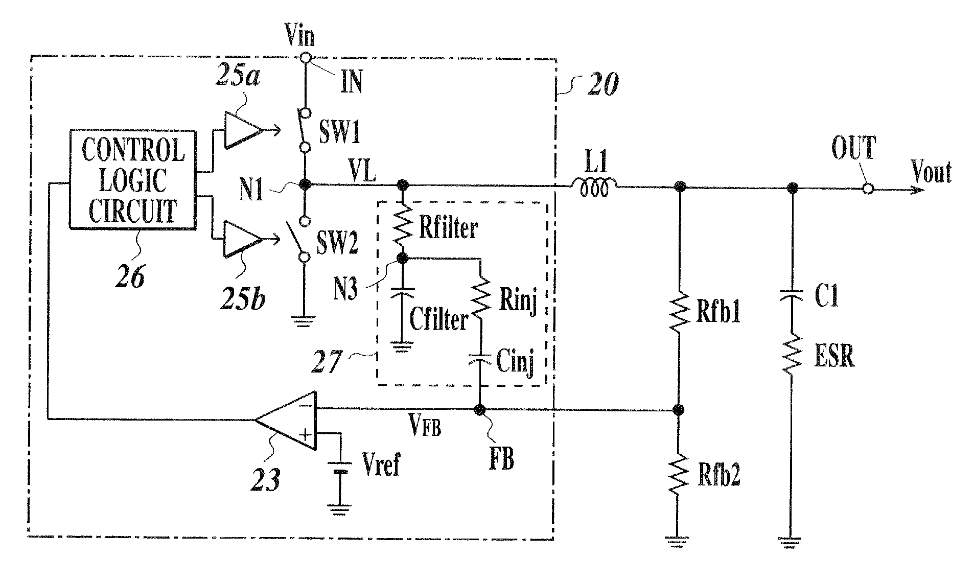
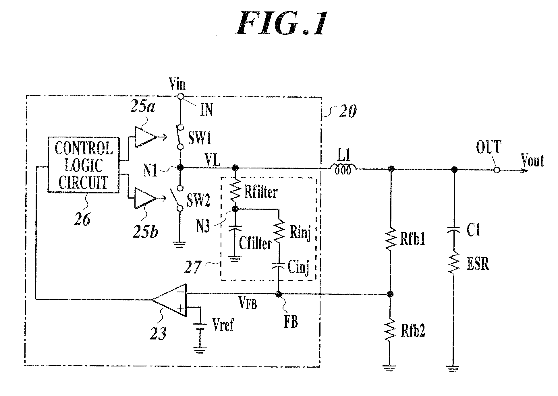
[0027]FIG. 1 illustrates embodiment of a DC-DC converter based on the switching regulator system according to the present invention.

[0028]The DC-DC converter of this embodiment includes an input terminal IN, a high-side driver switching element SW1, a low-side rectifier switching element SW2, a coil L1 as the inductor, a smoothing capacitor C1, an output terminal OUT, a switching control circuit 20, and series resistors Rfb1 and Rfb2.

[0029]While not specifically limited, among the circuits and elements configuring the DC-DC converter, the switching control circuit 20 may be formed on a semiconductor chip to give a power supply control IC (integrated circuit), and the coil L1 and the capacitor C1 may be connected to an external terminal of the IC. The switching elements SW1, SW2 herein may be on-chip elements provided inside the switching control circuit 20, or may be exte...


PUM


Abstract

Provided is a switched-mode power supply. The power supply includes: a DC voltage input terminal; a driver switching element connected to the input terminal; an inductor connected to the driver switching element; an output terminal connected to the inductor and outputting output voltage different from the input voltage; and an integrated circuit outputting control pulses used for on-off control of the driver switching element. The integrated circuit has: a ripple injection circuit adding a ripple component to a feedback voltage of the output voltage; a voltage comparator comparing the summed voltage with a predetermined voltage; and a control pulse generator generating the control pulse based on an output of the voltage comparator. The ripple injection circuit has an integrator outputting an integral of the voltage at the node between the driver switching element and the inductor, and a series RC circuit connected to the output end of the integrator.

Description

CROSS-REFERENCE TO RELATED APPLICATION[0001]The present U.S. patent application claims a priority under the Paris Convention of Japanese patent application No. 2011-100916 filed on Apr. 28, 2011, which shall be a basis of correction of an incorrect translation, and is incorporated by reference herein.BACKGROUND OF THE INVENTION[0002]1. Field of the Invention[0003]The present invention relates to a DC-DC converter which transforms DC voltage based on the switching regulator system, and in particular to a switched-mode power supply having a ripple injection function.[0004]2. Description of the Related Art[0005]DC-DC converter based on the switching regulator system has been known as a circuit which transforms DC input voltage into a different level of DC voltage. This sort of DC-DC converter has a driver switching element, a rectifier element, and a control circuit. The driver switching element applies DC voltage, received from a DC power supply such as a battery, to an inductor (coil...

Claims


Application Information

Patent Timeline
Patent Type & Authority Applications(United States)
IPC IPC(8): G05F1/46
CPCH02M2001/0025H02M3/156H02M1/0025
Inventor HIGUCHI, YOSHITAKANAKASHIMA, HEISUKEYAMANAKA, YUJI
Owner MITSUMI ELECTRIC CO LTD
Why Eureka
Try Eureka