Ethernet over power

a technology of overpowering and ethernet, applied in the direction of transmission, electrical apparatus, line transmission, etc., can solve the problems of not being equipped to serve any power management function, system not serving more than a very localized area of the ring main, and little uptake, so as to improve the functionality, save energy, and increase the functionality

Inactive Publication Date: 2012-11-01
HUGHES GLYN
View PDF1 Cites 67 Cited by
  • Summary
  • Abstract
  • Description
  • Claims
  • Application Information

AI Technical Summary

Benefits of technology

[0014]A major problem that the system of the present invention solves is that it integrates different types of functionality including inter alia datacomms and energy monitoring together in one multifunctional system. Unifying these functions provides the application drivers to develop new algorithms that, in the energy monitoring system for example, recognise different appliances when they are attached to the powerline. In turn this allows us to make intelligent on / off decisions for the user. The system can understand when a device is on standby for example and turn it off to save energy or when an appliance is unsafe and turn it off to avert appliance damage and or fire. The unifying of energy monitoring, energy control, data communications and audio / video communications has facilitated the design of an extraordinarily powerful and radical multi functional system.
[0016]According to a further aspect of the present invention there is provided a networked system comprising cable able to carry power and data, the system supplying low to medium voltage power at 240 v or below and comprising at least one Power and Data transmission terminal that is a MAC addressable power outlet, switch or transition point, the Power and Data transmission terminal having a PLC Transceiver, a microcontroller with memory, a power consumption meter and preferably with a transmission router between the microcontroller and the PLC Transceiver, the system thereby being able to both monitor energy usage and allow data communication over the powerline with a single microcontroller at the or each Power and Data transmission terminal.
[0017]The transmission router is in use located between at least two different low level data sources allowing multi source transmissions to be received and conveyed to a single comms chipset. This configuration enables construction of a truly multifunctional and very powerful system.
[0018]Preferably the system has a control panel that has a User Interface combined with a Microprocessor that translates the information provided by the sockets into user friendly, preferably graphical, information, and operability. User-centric software / algorithms for each application forms part of the system and increase it's functionality. Each of the functions provides synergy to the other. Energy monitoring and control, for example, allows us to develop algorithms that can make decisions which allow the system itself to save energy without human intervention and provides a much more powerful smart metering product.
[0019]The control panel User Interface provides the face of, and improves and adds to the functionality of each of the applications. Information on data transfer through the communications network for example can be accessed and controlled through the User interface, different source transmissions can be routed to different areas and appliances and a myriad other tasks can be performed in a very simple way. The control panel solves the problem of fragmented and difficult to access information by putting all the information and control in one place in a user friendly way. This interface and associated processor represent further novel and inventive aspects of the present invention in their own right separately of the Power and Data transmission terminal.
[0024]History functions and average appliance consumption functions can be monitored by a processor and linked database of the system and provide instant, easy to comprehend information that allows the user to react rapidly to changing appliance or user situations and mitigate at the very earliest opportunity any appliance or human anomalies or changed circumstance.

Problems solved by technology

Though ethernet-over-Power systems have had little uptake initially, there are now a number of limited scope LAN systems in use in the domestic / small office market sector.
Such systems do not, however, serve more than a very localized area within the ring main and are not equipped to serve any power management functions.
Whereas limited scope PLC data communications networks exist that use plug in adaptors these are uni-functional and generally inefficient.
Energy monitoring and information systems—(smart metering systems)—do also exist but are limited in scope to either whole house or single appliance information and existing control systems designed to switch on / off addressed sockets are all very limited in scope, as are existing systems designed to mitigate energy use by allowing the user to turn off the socket through infrared during standby.
None of the existing Ethernet-over-Power systems are able to satisfy multiple system applications and problems of the above type and users are generally left opting for one set of functionality or another.
Existing systems have been uni-functional in part because user datacomm transmission and energy and control transmissions each have different transmission sources and there can only be one comms chipset in any plug or socket otherwise it would be too expensive to produce and there would be transmission conflicts between the two comms micro processors.
The same problem exists at a lower level—two data sources in conflict attempting to communicate with one comms microprocessor.
To access even a major part of the different functionalities of existing uni-functional systems would necessitate at least two but possibly three different systems to be installed in a user's premises, the expense and logistics of which would be prohibitive.

Method used


Image

  • Ethernet over power
  • Ethernet over power
  • Ethernet over power

Examples


Embodiment Construction

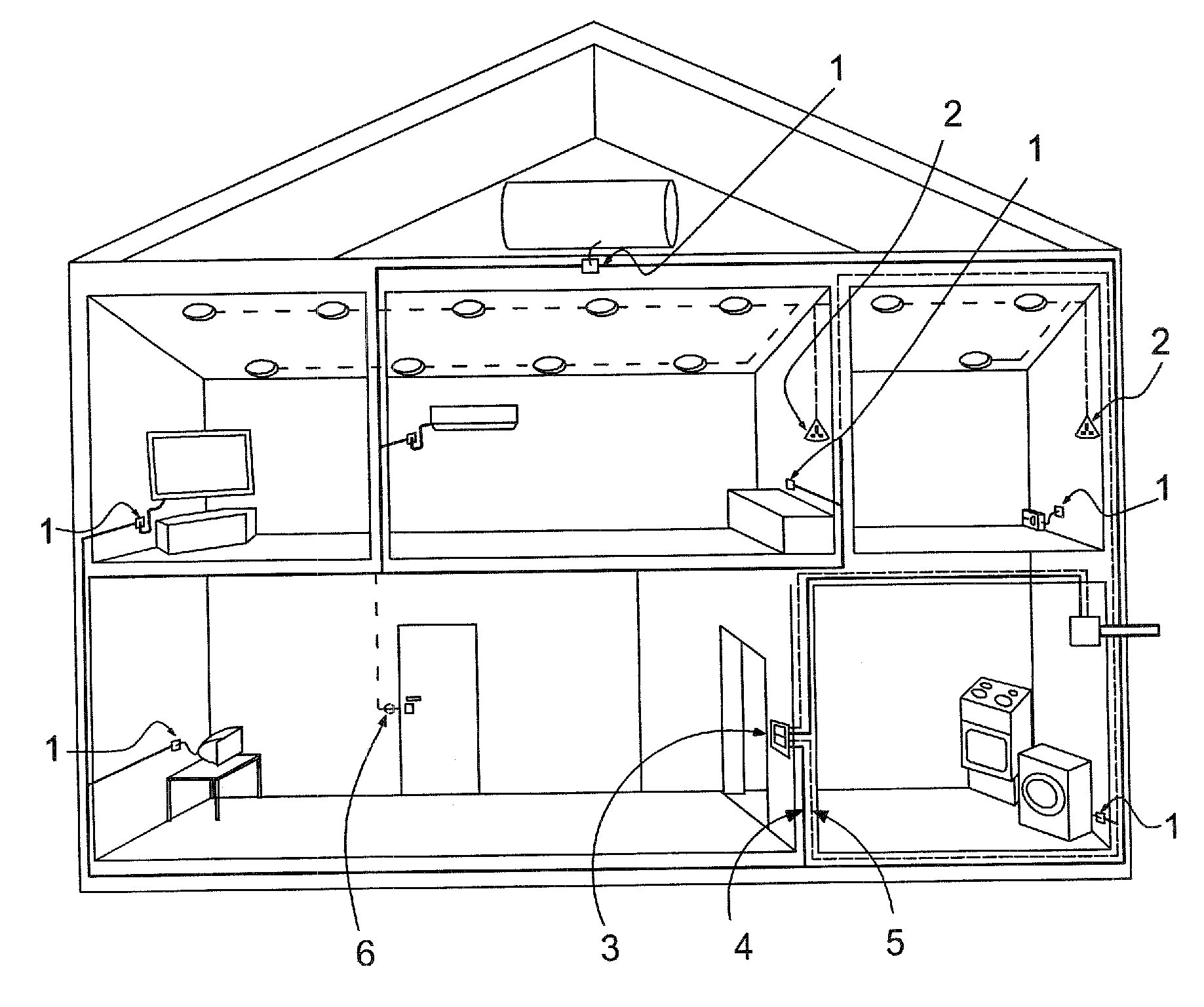
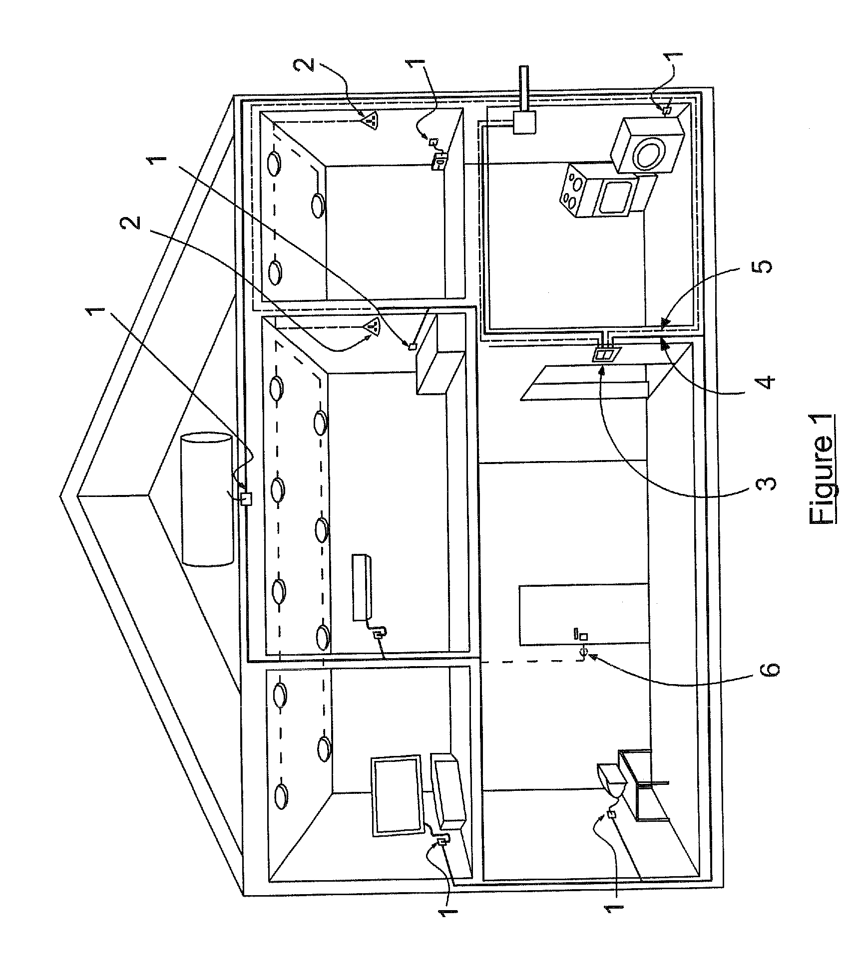
[0045]Referring firstly to FIG. 1, this shows an example system embodying the invention as installed in a two-story residential dwelling. This has a plurality of power sockets 1 for electrical plugs that are modified to be MAC addressable.

[0046]These are the ‘Class A’ IP addressable outlets and are linked by the corresponding ‘Class A’ power cabling 4. In addition to these ‘Class A’ IP addressable outlets 1 there are ‘Class B’ IP addressable outlets including those that use the lighting circuit such as the IP addressable light switches 2 illustrated in FIG. 1. A control panel 3 is provided to give control over the system and may, for example, allow control of doors to close / lock, lights to be monitored and turned off if not needed, power sockets the same et cetera. The locking of doors may use corresponding IP addressable door lock outlets 6.

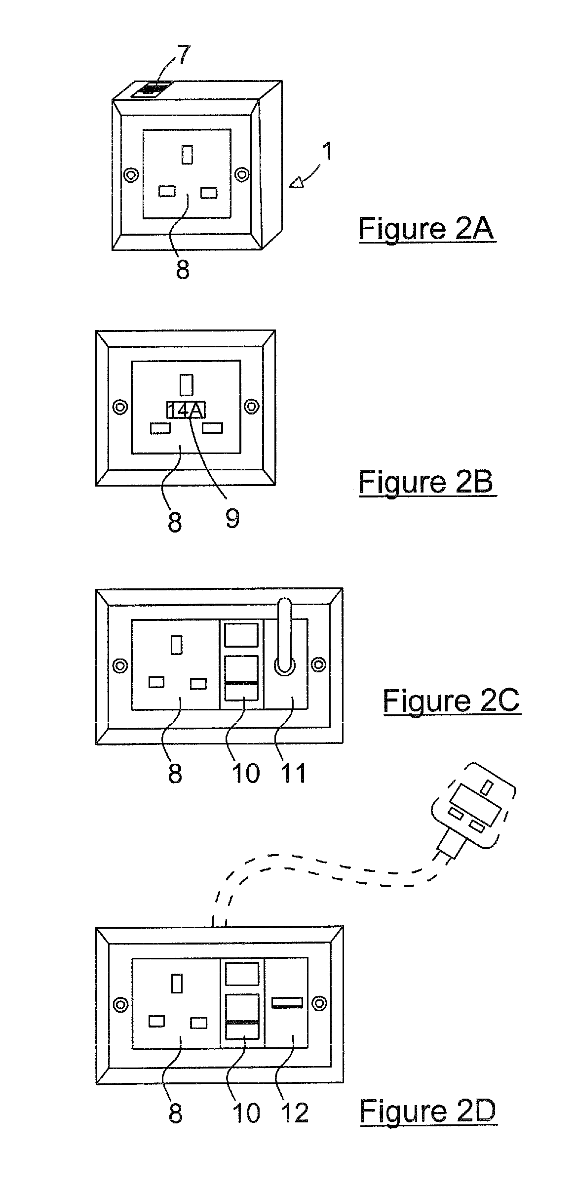
[0047]To serve as examples of the ‘Class A’ IP addressable outlets embodying the first aspect of the present invention nine variants of such ou...


PUM


Abstract

The present disclosure relates to Ethernet-over-Power and provides communication to and from the powerline hardware, e.g. power sockets or light fittings, and through the powerline itself. In one aspect a Power and Data transmission terminal that is a MAC addressable power outlet, switch or transition point is provided, the Power and Data transmission terminal having a PLC Transceiver, a microcontroller, a power consumption meter and a transmission router between the microcontroller and the PLC Transceiver, the system thereby being able to both monitor energy usage and allow data communication over the powerline with a single microcontroller at the or each Power and Data transmission terminal. The system provides I. P addresses to the electrical outlets from which a wide range of devices run and in so doing it can communicate with the electrical outlets themselves.

Description

FIELD OF THE INVENTION[0001]The present invention concerns improvements in and relating to Ethernet-over-Power and provides communication to and from the powerline hardware, e.g. power sockets, and through the powerline itself.BACKGROUND TO THE INVENTION[0002]Ethernet-over-Power adaptors, or Internet Protocol (IP)-over-power adaptors as they are alternatively known, have been in existence for the past 20 years. Such adaptors plug into power sockets and modulate low voltage data signals in order that they can be transmitted along medium voltage power cabling thereby providing an opportunity to reduce the need for dedicated (twisted pair) data cabling to be installed / used and providing a more secure alternative or supplement to wireless data transmission in Local Area Network (LAN) systems. Electrical cable is generally more stable than twisted pair cable and has the potential to offer great benefits Some grand IP-over-Power proposals have also been made in the company side of the ele...

Claims


Application Information

Patent Timeline
Patent Type & Authority Applications(United States)
IPC IPC(8): H04B3/54
CPCH04B3/542H04B2203/5454H04B2203/5445
Inventor HUGHES, GLYN
Owner HUGHES GLYN
Why Eureka
Try Eureka