Auto grid moving device for diagnostic x ray table

a technology of x-ray imaging and moving device, which is applied in the field of configuration of grid for x-ray imaging device, can solve the problems of grid docking device space occupation, time-consuming operation of this configuration, and operator's difficulty in pushing in or pulling out the grid

Inactive Publication Date: 2012-11-01
GE MEDICAL SYST GLOBAL TECH CO LLC
View PDF6 Cites 3 Cited by
  • Summary
  • Abstract
  • Description
  • Claims
  • Application Information

AI Technical Summary

Problems solved by technology

This configuration and operation suffers from several deficiencies.
First, the operator may sometimes have difficulty pushing in or pulling out the grid as a result of not being able to locate the grid-in slot when performing such operation.
The operation of this configuration is also time consuming.
Meanwhile, a grid docking device takes up space.
Furthermore, frequent pushing in and pushing out of the grid may cause damage.

Method used


Image

  • Auto grid moving device for diagnostic x ray table
  • Auto grid moving device for diagnostic x ray table
  • Auto grid moving device for diagnostic x ray table

Examples


Embodiment Construction

[0014]The present disclosure will describe embodiments of the present invention, however, the present disclosure is not meant to be limited by the embodiments.

[0015]The embodiments of the present invention will be described in detail in combination with the figures, wherein the embodiments are not meant to limit the present invention, and wherein like numbers in the figures represent like parts.

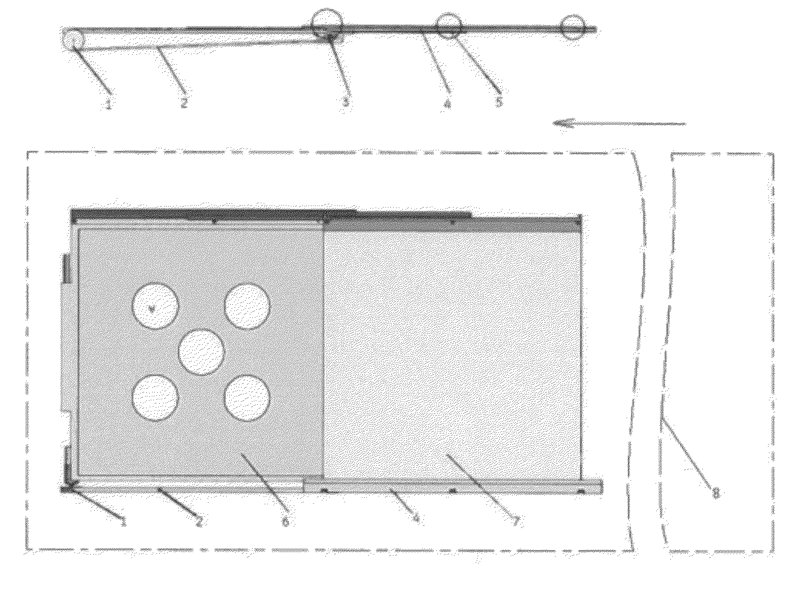
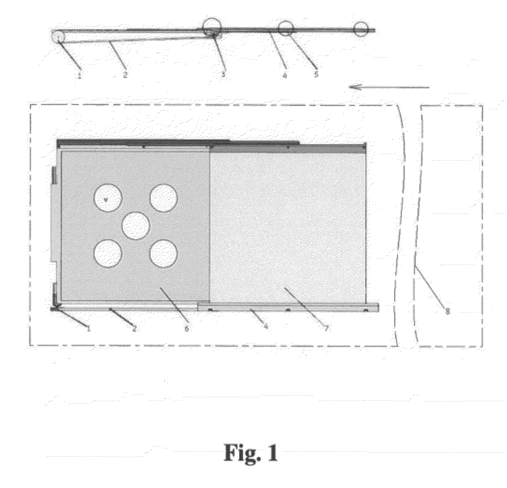
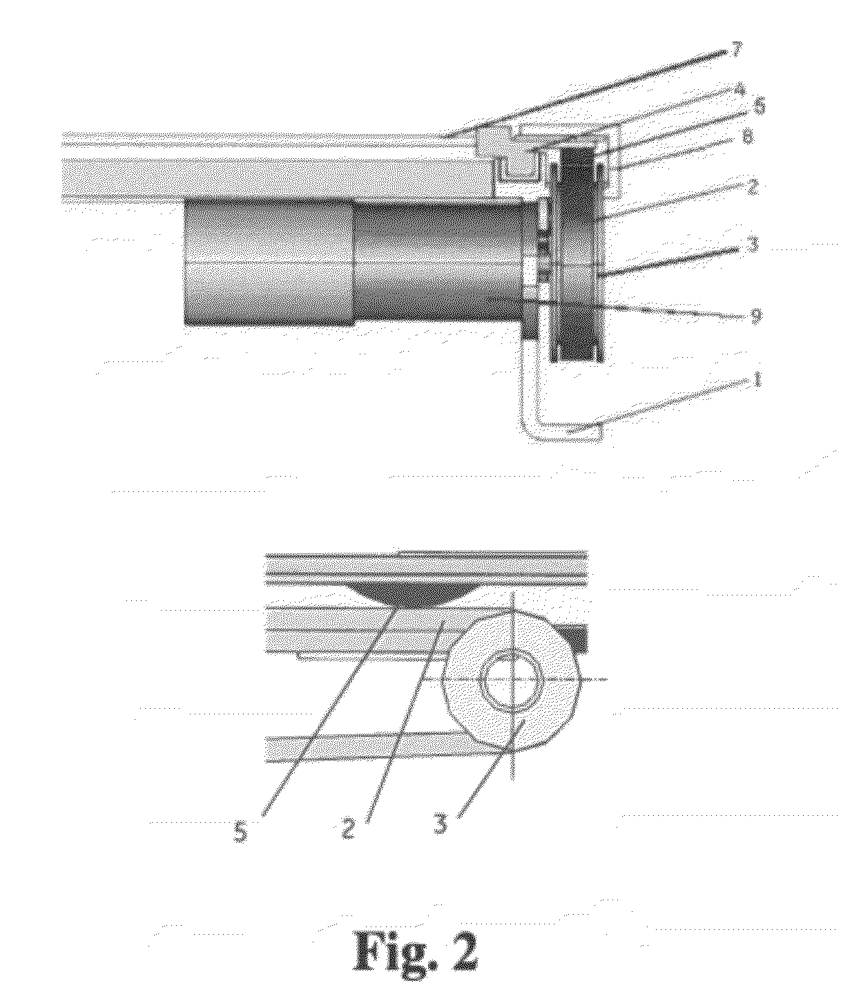
[0016]FIG. 1 shows the front view (top of FIG. 1) and top view (bottom of FIG. 1) of an auto grid moving apparatus. The auto grid moving apparatus is located beneath a table 8. A grid 7 is driven by the auto grid moving apparatus and is able to move back and forth between the table 8 and an ion chamber 6 beneath the table 8. The apparatus makes use of a double sided timing belt 2. The timing belt 2 gears with two timing wheels 1 and 3 at two ends of its inner side face, wherein a motor is disposed on one of the timing wheels 1 to drive the timing belt 2. The outer side face of the timing belt...


PUM


Abstract

An auto grid moving apparatus for an X ray imaging device is provided. The apparatus includes: a grid; a grid holder on which the grid is disposed; a fixing base; and a double sided timing belt geared with at least two timing wheels at the two ends of the timing belt on the inner side face of the timing belt and geared with the grid holder at the outer side face of the timing belt, wherein one of the timing wheels has a motor disposed thereon, the motor being configured to drive the timing wheel to move the timing belt and to drive the grid holder to move.

Description

BACKGROUND OF THE INVENTION[0001]1. Field of the Invention[0002]The field of the invention relates to the configuration of a grid for an X ray imaging device.[0003]2. Description of Related Art[0004]The grid for an X ray imaging device is generally mountable onto an X ray detector housing, from which the operator can push in or pull out the grid as needed. Usually, the operator has to pull out the grid from the detector housing of the X ray imaging device bed for pediatric and extremity X ray inspections; and push back in for other X ray inspections. This configuration and operation suffers from several deficiencies. First, the operator may sometimes have difficulty pushing in or pulling out the grid as a result of not being able to locate the grid-in slot when performing such operation. The operation of this configuration is also time consuming. Meanwhile, a grid docking device takes up space. Furthermore, frequent pushing in and pushing out of the grid may cause damage.[0005]To so...

Claims


Application Information

Patent Timeline
Patent Type & Authority Applications(United States)
IPC IPC(8): G21K1/00
CPCA61B6/0457A61B6/4291A61B6/583A61B6/0487
Inventor LI, YUQINGLI, FUSHENGJIA, YINGJIEXI, WEINING
Owner GE MEDICAL SYST GLOBAL TECH CO LLC
Why Eureka
Try Eureka