
Highly flexible printed alkaline batteries based on mesh embedded electrodes

a technology of printed alkaline batteries and embedded electrodes, applied in the field of flexible batteries, can solve the problems of insufficient progress of flexible batteries, and inability to achieve similar advancements in flexible batteries

Inactive Publication Date: 2012-11-01
PALO ALTO RES CENT INC
View PDF1 Cites 37 Cited by
  • Summary
  • Abstract
  • Description
  • Claims
  • Application Information

AI Technical Summary

Benefits of technology

The patent describes a flexible battery and a method to make it. The battery has a flexible anode and cathode, with an electrolyte in between. The anode and cathode are made by embedding the electro-active material in a mesh material and associating a current collector with it. The arrangement is then sealed. The technical effect of this patent is to provide a flexible battery that can be easily made and used.

Problems solved by technology

However, it is also understood that such flexible electronic devices cannot reach their full realization until flexible batteries are developed that match device form-factor and power requirements of flexible electronic devices.
Flexible batteries share several manufacturing challenges with their application to flexible electronics, including the thermal budget imposed by plastic substrates, compatibility issues of different layers in the device and stability during bending.
While there has been progress in these areas as applied to flexible electronics, a similar level of advancement has not been achieved in flexible batteries.
Similar principles, however, are not as useful for flexible batteries because cell capacity of a battery is directly related to the amount of electro-active material present in the battery.
Such thin film batteries have very low capacity.
However, even with low thickness there is a limit of the flexibility and bend radius of such a battery.
Metallic oxides in the configuration of thin foils, which form the active anode, are very brittle and crumble after few flexing cycles.
Thus existing flexible batteries are limited by the required tradeoff between battery capacity needs and the flexibility needs.

Method used


Image

  • Highly flexible printed alkaline batteries based on mesh embedded electrodes
  • Highly flexible printed alkaline batteries based on mesh embedded electrodes
  • Highly flexible printed alkaline batteries based on mesh embedded electrodes

Examples


Embodiment Construction

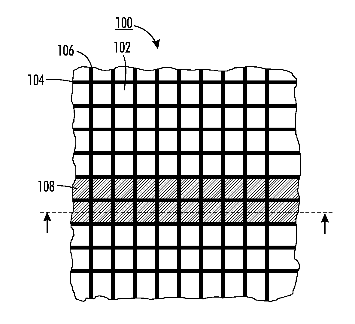
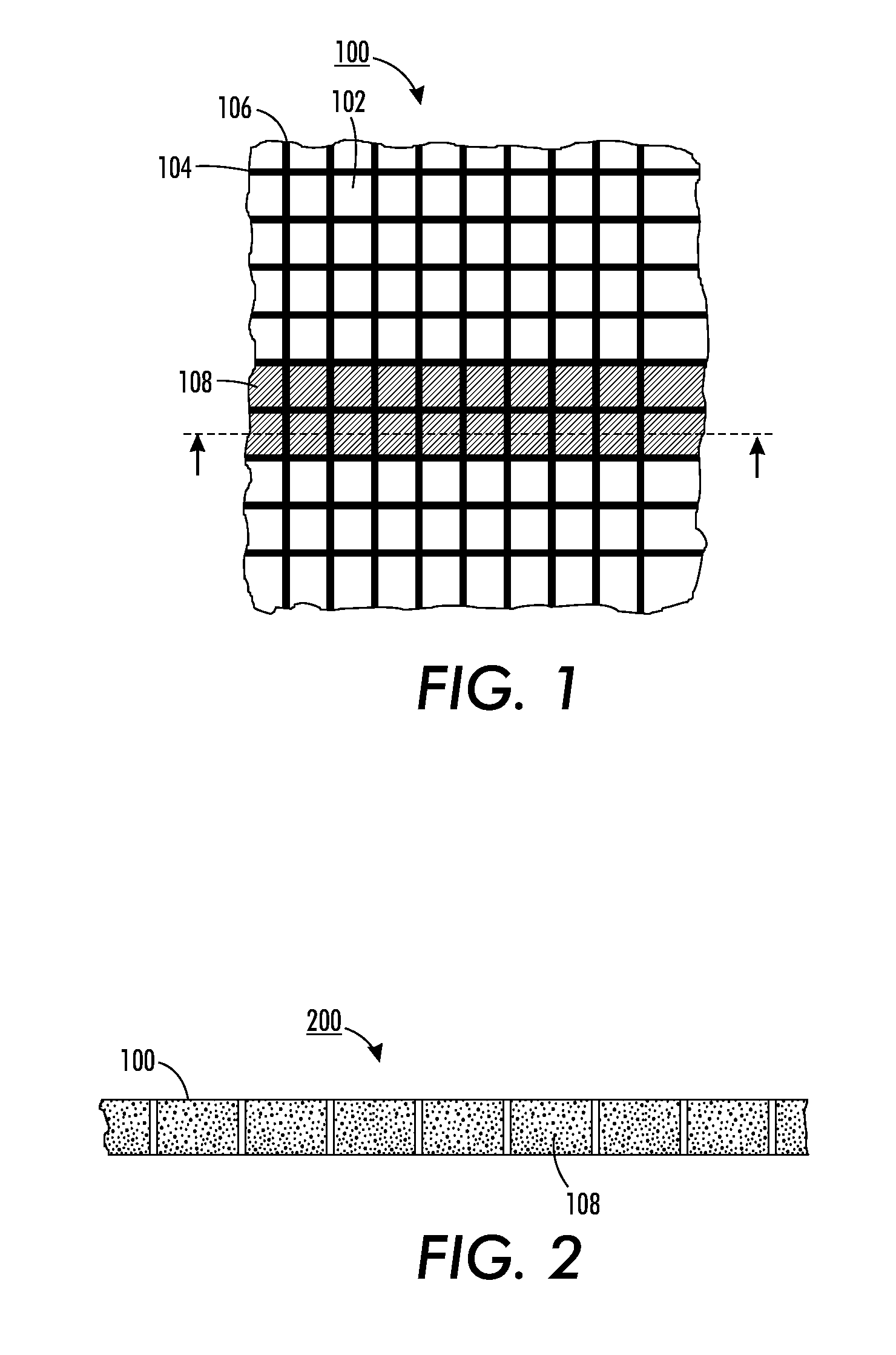
[0018]FIG. 1 illustrates a substrate in the form of a mesh material 100 having a plurality of voids 102 defined by horizontal lines or wires 104 and vertical lines or wires 106. An electrode of a flexible battery according to the present application is formed by filling voids 102 of mesh material 100 with an electro-active material 108 (for description purposes only some of the voids 102 are shown as having been filled in FIG. 1). FIG. 2 illustrates mesh material 100 in cross-section at voids 102 which have been filled by electro-active material 108, such as in the form of an ink slurry.

[0019]Mesh material 100 may be a conductive mesh or a non-conductive mesh, i.e., horizontal lines or wires 104 and vertical lines or wires 106 may be made of conductive or non-conductive material. A conductive mesh is configured of any appropriate conductive material including but not limited to stainless steel (SS), nickel, or silver, among others. The non-conductive mesh is configured of any approp...


PUM

PropertyMeasurementUnit
thicknessaaaaaaaaaa
thicknessaaaaaaaaaa
current densityaaaaaaaaaa

Abstract

A flexible battery and a method to form the flexible battery include forming an anode by embedding an anode type electro-active material within a mesh material and associating an anode current collector with the anode. Similarly a cathode is formed by embedding a cathode type electro-active material within a mesh material and a cathode current collector is associated with the cathode. An electrolyte is located between the anode and cathode, and the arrangement is sealed.

Description

BACKGROUND[0001]The present application is directed to batteries, and more particularly flexible batteries and the process for making such flexible batteries.[0002]There is a great deal of interest in the development of folding, conformable electronic devices. It has been shown that flexible electronic devices would be useful for a wide range of functionality such as digital memory, photovoltaic cells, displays, pressure sensors, implantable medical devices, light emitting diodes, RFID tags, smart cards, self-powered portable devices, microelectronics, and thin film transistors, among others. However, it is also understood that such flexible electronic devices cannot reach their full realization until flexible batteries are developed that match device form-factor and power requirements of flexible electronic devices.[0003]Flexible batteries share several manufacturing challenges with their application to flexible electronics, including the thermal budget imposed by plastic substrate...

Claims


Application Information

Patent Timeline
Patent Type & Authority Applications(United States)
IPC IPC(8): H01M10/02H01M10/04H01M6/02H01M4/04
CPCH01M4/0416H01M4/244H01M4/48H01M4/50H01M4/74Y10T29/49115H01M10/34H01M2010/0495Y10T29/4911Y10T29/49108H01M10/0436Y02E60/10Y02P70/50
Inventor GAIKWAD, ABHINAV M.WHITING, GREGORY LEWIS
Owner PALO ALTO RES CENT INC
Learn More