Fuel Cell System Having a Fluid Separator in the Anode Circuit

a fuel cell and fluid separator technology, applied in the field of fuel cell systems with an anode circuit, can solve the problems of system restart malfunction, risk of freezing, droplets tending to condensate out, etc., and achieve the effect of simple, safe and reliable operating structure of the anode circuit, compact configuration and avoiding freezing

Inactive Publication Date: 2012-11-01
DAIMLER AG
View PDF3 Cites 2 Cited by
  • Summary
  • Abstract
  • Description
  • Claims
  • Application Information

AI Technical Summary

Benefits of technology

[0005]Exemplary embodiments of the present invention are directed to a fuel cell system with an anode circuit that avoids the disadvantages described above and provides a simple, safe and reliably operating structure for the anode circuit.
[0006]In accordance with exemplary embodiments of the present invention, freshly supplied hydrogen is introduced into the region of the liquid separator so that any liquid remaining in the gas stream, which condenses out of the fresh and, owing to its expansion from a high pressure, typically very cold gas, condenses directly in the liquid separator and can therefore remain therein. In this configuration, the liquid separator is integrated with the recirculation delivery device. This prevents the feed of condensed-out liquid to line elements that could then freeze. The integration with the recirculation delivery device to form an integrated assembly further allows a very compact configuration to be obtained.
[0007]In a particularly useful and advantageous further development of the configuration according to the invention, the liquid separator integrated with the recirculation delivery device is placed downstream of the recirculation delivery device in the direction of flow of the recirculated gas stream. As a result, the freshly supplied hydrogen stream does not have to be routed through the recirculation delivery device, and the condensed-out water is primarily separated in the liquid separator.
[0008]In a correspondingly advantageous further development of the invention, a second liquid separator which is connected to the first liquid separator is provided in the anode circuit, the second liquid separator being located upstream of the recirculation delivery device in the direction of flow of the recirculated gas stream. As a result, only the liquid condensed out by the fresh hydrogen gas stream has to be separated in the first liquid separator, while the liquid discharged from the anode region can, for example, be separated out in the second separator. With this configuration, the product water, which will constitute the major part of separated water in the recirculated gas stream, can be separated before reaching the recirculation delivery device and therefore does not have to be conveyed through the recirculation delivery device in an energy-intensive manner. Downstream of the recirculation delivery device, the part of the liquid that has been condensed out owing to the fed-in fresh hydrogen and the temperature reduction involved is then separated in the liquid separator integrated with the recirculation delivery device, and the recirculation fan always runs dry, avoiding the risk of freezing. As the liquid separators are connected to each other, it is enough to discharge the water from the anode circuit using a single line element with a valve device, so that the need for interfaces—which are very sensitive to sealing problems, in particular with respect to the hydrogen feed—is reduced.
[0009]In a very advantageous and useful further development of the invention, both liquid separators can be integrated with the recirculation delivery device into an assembly, which provides a particularly compact configuration. Owing to the comparatively large mass of the integrated assembly, this will cool more slowly than the surrounding line elements, thereby minimizing the risk that liquid could condense out in the region of the assembly. In addition, further interfaces and line elements can be saved, which is a significant advantage in terms of costs and assembly work, in particular with respect to the interfaces which have to be sealed against the hydrogen present in the line elements.
[0010]The fuel cell system according to the invention can therefore be equipped with an anode circuit that operates reliably even at temperatures below freezing point and requires a minimum of interfaces and components. Such a simple, cost-effective and reliable configuration is predestined for use in a vehicle. The preferred application of the fuel cell system according to the invention is therefore the use of the fuel cell system in a vehicle for supplying electric energy to drive units and / or secondary loads.

Problems solved by technology

This has the disadvantage that droplets tend to condensate out in the line section between these two components and may return into the region of the valve and / or the recirculation delivery device.
If such a fuel cell system is now switched off at temperatures below freezing point, the condensed-out water may freeze, resulting in malfunction or leakage when the system is restarted.
The integration of the separator upstream of the recirculation delivery device in the direction of flow into the inflow region has the disadvantage that a great amount of water in involved, so that here, too, there is a risk of freezing.

Method used


Image

  • Fuel Cell System Having a Fluid Separator in the Anode Circuit
  • Fuel Cell System Having a Fluid Separator in the Anode Circuit

Examples


Embodiment Construction

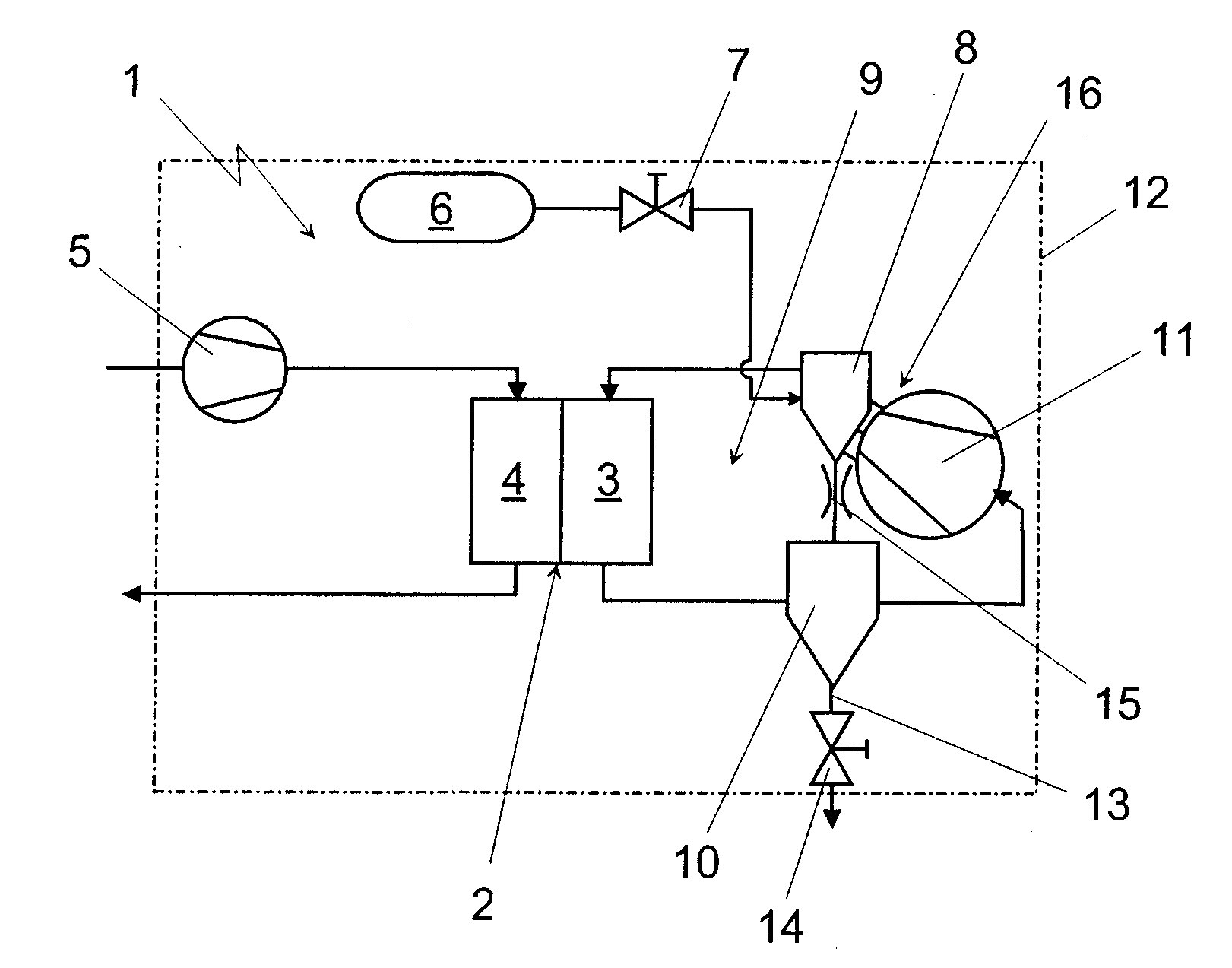
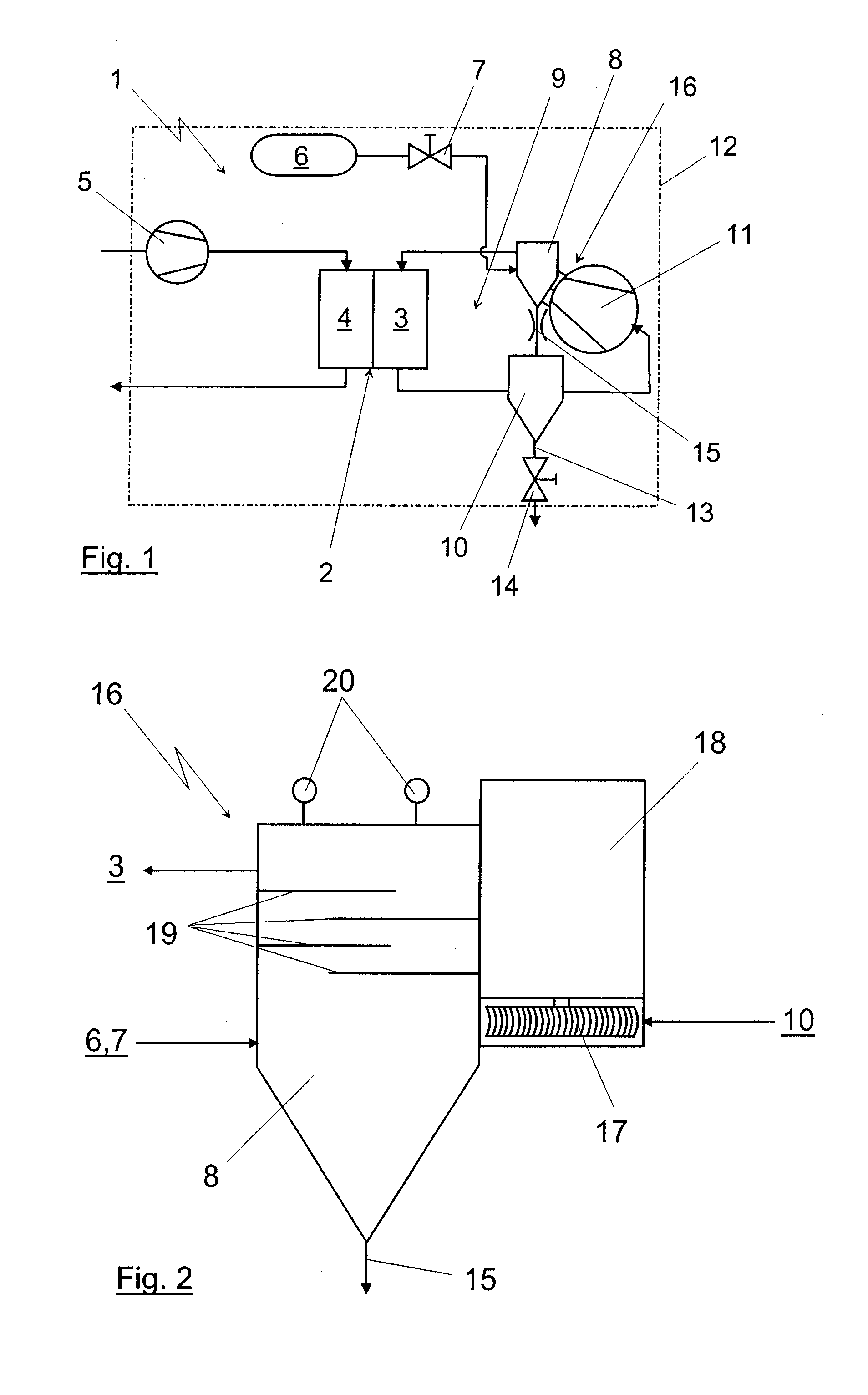
[0015]The illustration of FIG. 1 shows a fuel cell system 1, the core of which is a fuel cell 2 having an anode region 3 and a cathode region 4, and which may for example be a stack of PEM fuel cells. Air as an oxygen-containing gas is supplied to the cathode region 4 via an air delivery device 5. The air discharged from the cathode region 4 can be discharged to the environment either directly or via components not shown in the drawing, for example a burner, a turbine or the like.

[0016]The anode region 3 is supplied with hydrogen from a compressed-gas accumulator 6 in which the hydrogen is stored as a gas under high pressure. The hydrogen flows via a shut-off valve 7, in the region of which it is expanded, into a liquid separator 8 (described in detail below) and into the anode region 3. From the anode region 3, the unused residual gas flows in an anode circuit 9 via a second liquid separator 10 and a recirculation delivery device 11 into the region of the water trap 8 and can there...


PUM

PropertyMeasurementUnit
electric energyaaaaaaaaaa
pressure lossaaaaaaaaaa
freezingaaaaaaaaaa

Abstract

A fuel cell system includes an anode circuit by means of which unused gas from the anode region of a fuel cell can be recirculated via a recirculation delivery device into the anode region. At least one liquid separator is provided in the anode circuit. The liquid separator is integrated with the recirculation delivery device to form an assembly. Fresh hydrogen is supplied to the anode region by feeding the hydrogen into the liquid separator.

Description

BACKGROUND AND SUMMARY OF THE INVENTION[0001]The invention relates to a fuel cell system with an anode circuit.[0002]From general prior art, it is known to provide anode circuits in fuel cell systems, by means of which anode circuits unused exhaust gas from the anode region of the fuel cell can be recirculated and then fed to the anode region of the fuel cell together with fresh hydrogen. To compensate for the pressure loss occurring in the anode region, a recirculation delivery device is required in the region of such an anode circuit. This may in principle consist of a fan, a compressor or the like. It would, however, be conceivable to design this device in such a way that the incoming fresh hydrogen draws the recirculated gas stream in the manner of a jet pump. A combination of such recirculation delivery devices is also conceivable.[0003]Typically, however, a fan is used as recirculation delivery device. In order to operate such a fan safely and reliably and to prevent a freezin...

Claims


Application Information

Patent Timeline
Patent Type & Authority Applications(United States)
IPC IPC(8): H01M8/04H01M8/06
CPCH01M8/04097H01M8/04164Y02T90/32Y02E60/50H01M2250/20Y02T90/40
Inventor BAUR, THOMASRICHTER, HOLGER
Owner DAIMLER AG
Why Eureka
Try Eureka