
Dual braid reinforcement deflectable device

a deflectable device and braid technology, applied in the field of braided shafts, can solve the problems of reducing the total amount of space available for additional wiring, prior art catheter construction, etc., and achieve the effect of reducing the total amount of spa

Active Publication Date: 2012-11-01
ST JUDE MEDICAL ATRIAL FIBRILLATION DIV
View PDF7 Cites 99 Cited by
  • Summary
  • Abstract
  • Description
  • Claims
  • Application Information

AI Technical Summary

Benefits of technology

[0012]It has been recognized that there are a number of disadvantages associated with some implementations of prior art catheter construction. First, the steering wires inserted into the internal lumen of the shaft are often held in place via a secondary liner using a re-melt / reflow process that adheres the wires to the inside surface of the lumen. In some applications, these wires can delaminate from the inside surface of the internal lumen. In addition, placement of the steering wires within the internal lumen reduces the total amount of space that is available for additional wiring, irrigation, and / or passage of devices there through. This is especially acute in an introducer, where another catheter must pass through this lumen.
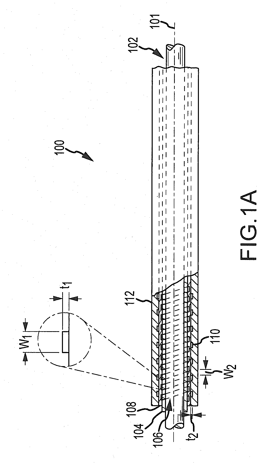
[0013]The present invention overcomes a number of the disadvantages associated with prior art catheter shaft construction to provide an improved catheter shaft. In particular, the present invention allows for the insertion of one or more steering wires between an inner braid and outer braid of a dual braided catheter shaft, thereby encapsulating the steering wire(s) in a sidewall of the catheter shaft. This provides a robust attachment of the steering wire to the catheter shaft and removes the steering wires from the internal lumen to a position within the sidewall of the catheter shaft. Accordingly, this may increase the available space within the lumen for other uses.
[0018]In accordance with a further aspect of the present invention, a method for use in constructing a catheter shaft involves serial application of a number of layers to form a dual braided shaft. The method includes forming a first cylindrical layer of polymer material on a mandrel and braiding or winding a first wire on an outside surface of this first cylindrical layer. While the first wire is wound about first cylindrical layer of polymer, one or more pull wires may be disposed along an outside surface of this inner braid. At this time, a second wire may be wound about the outside surface of the inner braid and the pull wires to form an outer braid such that the pull wire(s) is encapsulated between the inner braid and outer braid. An additional outer layer of polymer may then be formed on the outside surface of the second braided wire. It will be appreciated that the dual braided shaft can be formed in a continuous process to define an integral system with potentially improved mechanical properties. Further, these mechanical properties of the shaft can be varied along the length of the shaft by changing the braiding parameters when braiding or winding the first and / or second wires. Thus, a dual braided shaft with variable properties along the length thereof can be formed in a continuous flow process thereby reducing construction complexity and cost.

Problems solved by technology

It has been recognized that there are a number of disadvantages associated with some implementations of prior art catheter construction.
In addition, placement of the steering wires within the internal lumen reduces the total amount of space that is available for additional wiring, irrigation, and / or passage of devices there through.

Method used


Image

  • Dual braid reinforcement deflectable device
  • Dual braid reinforcement deflectable device
  • Dual braid reinforcement deflectable device

Examples


Embodiment Construction

[0030]In the following description, the invention is set forth in the context of specific implementations involving separate construction sequences for a dual braided catheter shaft and / or the incorporation of one or more pull / steering wires between inner and outer braids of the shaft, followed by assembly of those components to realize a steerable catheter. The catheter may include irrigation lumens and ports. It may also include medical elements, such as ablation elements (electrodes, transducers), sensors (electrodes, magnetic coils, thermistors) and the like. While this is an advantageous implementation of the invention, and serves to illustrate the various aspects of the invention, it should be appreciated that the invention is not limited to this catheter application, this type of catheter shaft or the illustrated construction techniques. Accordingly, the description below should be understood as exemplifying the invention and not by way of limitation.

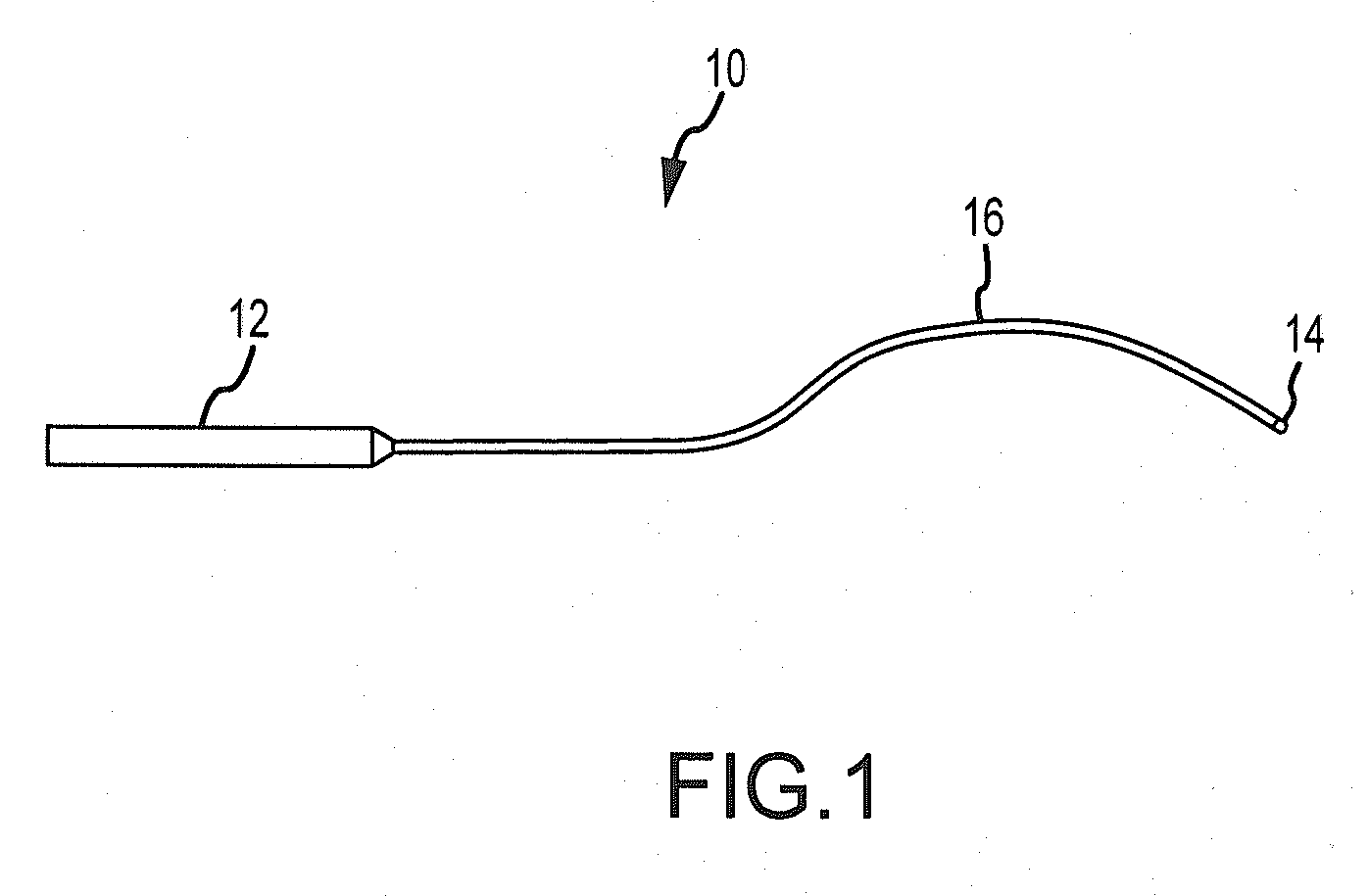
[0031]FIG. 1 shows an cat...


PUM

PropertyMeasurementUnit
diameteraaaaaaaaaa
width w3aaaaaaaaaa
width w3aaaaaaaaaa

Abstract

A dual braided catheter shaft includes an inner helical braid and outer helical braid than encapsulate an axially extending steering wire there between. In one embodiment, the shaft includes an inner polymer jacket, an inner braid formed on the inner jacket, a steering wire disposed along an outside surface of the inner braid, an outer braid formed over the inner braid and steering wire assembly and an outer jacket formed on the outer braid. The braiding parameters of the inner and outer braids can be varied along the length of the catheter to provide varying mechanical properties.

Description

CROSS-REFERENCE TO RELATED APPLICATIONS[0001]This application is a continuation-in-part of U.S. application Ser. No. 11 / 618,570, filed 29 Dec. 2006, now pending (the '570 application). The '570 application is hereby incorporated by reference in its entirety as though fully set forth herein.BACKGROUND OF THE INVENTION[0002]a. Field of the Invention[0003]The present invention relates generally to catheter shafts and, in particular, to a dual braided shaft with one or more pull or steering wires encapsulated between braid layers of the dual braided shaft.[0004]b. Background Art[0005]Various medical fields use different types of catheters and introducers (collectively referred to herein as “catheters”) to achieve access to a physiological site for a medical procedure. For example, electrophysiology catheters are typically threaded through a blood vessel of a patient to reach a desired site for a medical procedure. In the diagnosis and treatment of atrial fibrillation, a catheter may be ...

Claims


Application Information

Patent Timeline
Patent Type & Authority Applications(United States)
IPC IPC(8): A61M25/092B32B37/02
CPCA61M25/0012A61M25/0045A61M25/005A61M25/0053B29C53/58A61M25/0147A61M2025/0059B29L2031/7542A61M25/0054
Inventor FUENTES, ALLAN M.
Owner ST JUDE MEDICAL ATRIAL FIBRILLATION DIV
Learn More