Method of improving the efficiency of loosely packed solar cells in dense array applications

a solar cell and dense array technology, applied in the field of solar cell array assembly, can solve the problems of low efficiency of solar cells, and low efficiency of solar cells, and achieve the effect of maximum utilization

Inactive Publication Date: 2012-11-08
GARBOUSHIAN VAHAN +1
View PDF2 Cites 33 Cited by
  • Summary
  • Abstract
  • Description
  • Claims
  • Application Information

AI Technical Summary

Problems solved by technology

Furthermore the entire front surface area of the cell may not be active due to the necessity of a front surface contact to which the ribbons are bonded.
Excessive spacing might lead to a slightly higher manufacturing cost due to a larger than necessary substrate, and a marginally lower system efficiency, but from a practical standpoint packing density is not a major concern for one sun solar panels.
Concentrator PV systems, systems which use ancillary optics to intensify the light striking the solar cell, make the available illuminated area a cost driven commodity since the light striking the solar cells is no longer free, but has been preconditioned by costly hardware.
Every bit of concentrated sunlight that falls between the active areas of solar cells is lost, resulting directly in reduced system efficiency.

Method used


Image

  • Method of improving the efficiency of loosely packed solar cells in dense array applications
  • Method of improving the efficiency of loosely packed solar cells in dense array applications
  • Method of improving the efficiency of loosely packed solar cells in dense array applications

Examples


Embodiment Construction

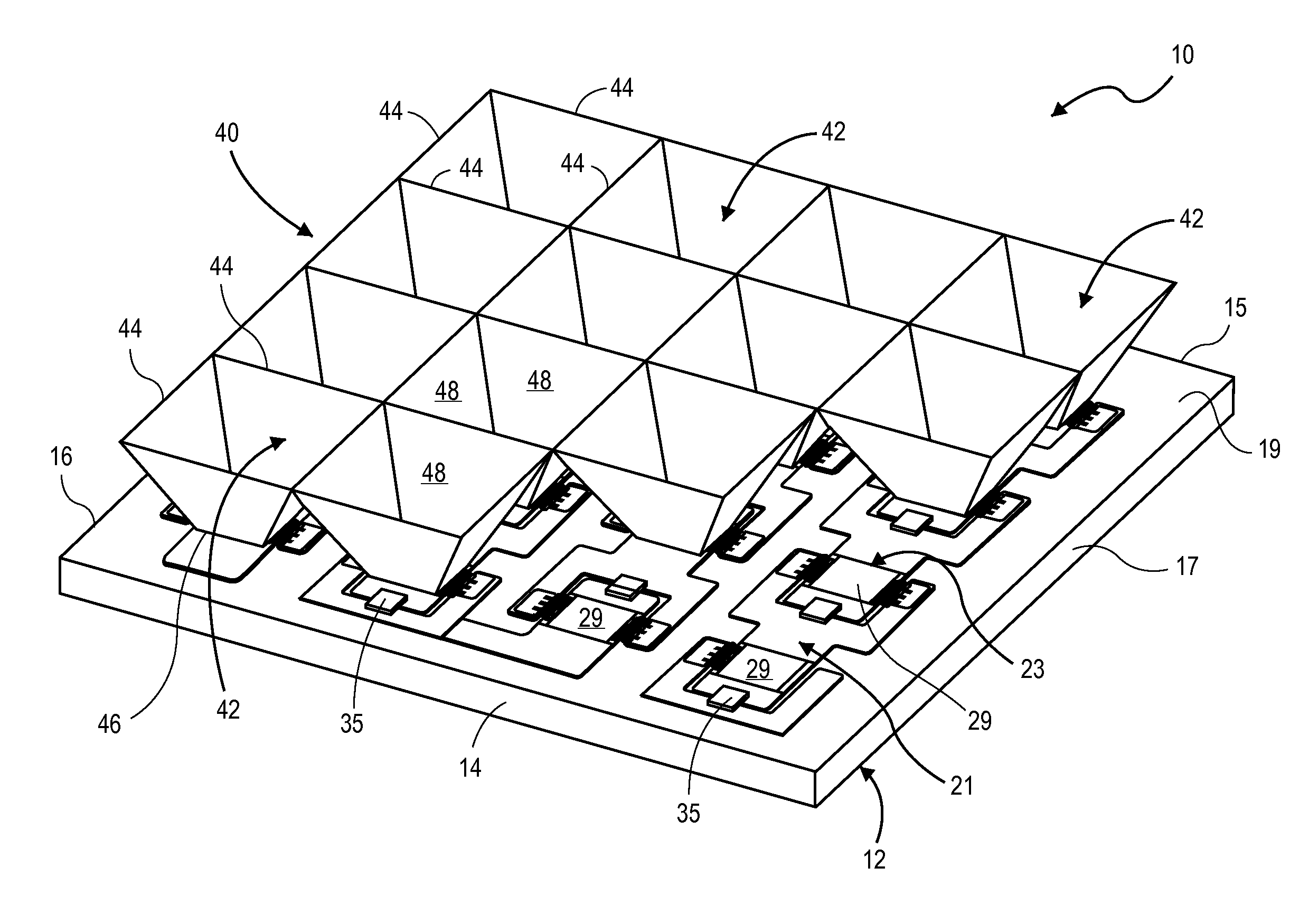
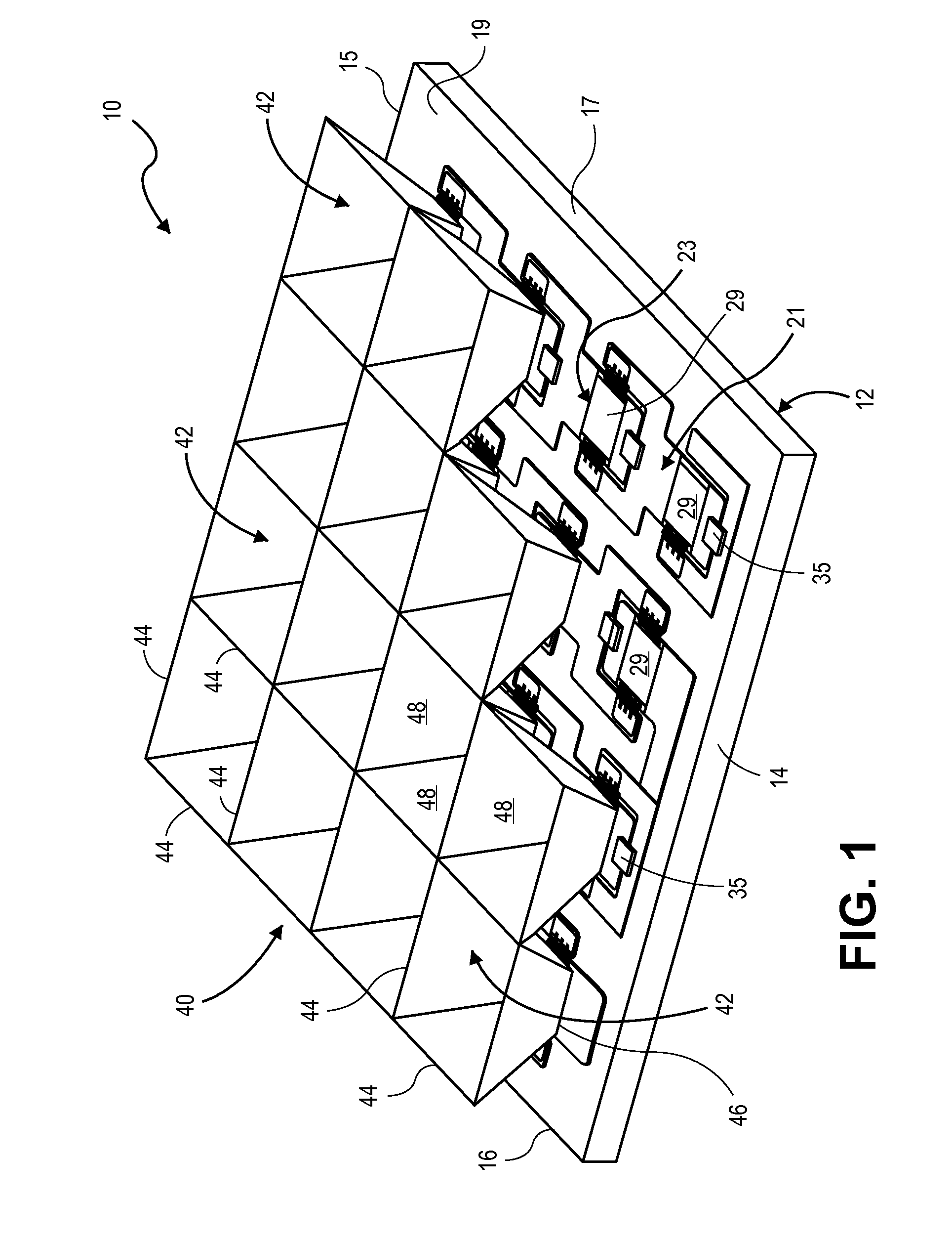
[0012]The increased efficiency Concentrator Photovoltaic (PV) System will now be described by referring to FIGS. 1 and 2 of the drawings. The PV System is generally designated numeral 10. It has a substrate 12 having a front end 14, a rear end 15, a left end 16, a right end 17 and a top surface 19. Substrate 12 may be made of a non-electrical conducting material or a conducting material such as metal in which the top surface has been rendered non-conductive by application of a surface treatment or coating on the non-conductive material.

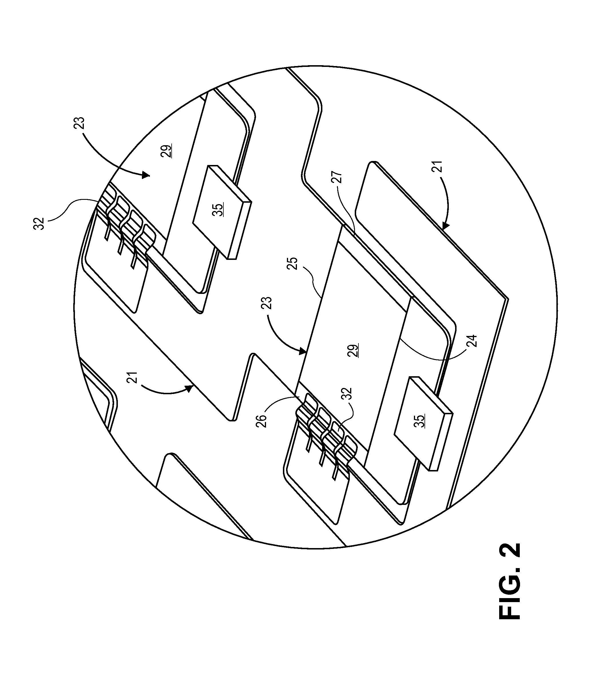
[0013]A plurality of metal traces 21 are located on top surface 19 and they provide a surface upon which the solar cells 23 can be supported and also provide a path for the electrical output of the individual solar cells 23. The solar cells 23 have a front edge 24, a rear edge 25, a left edge 26, a right edge 27 and a top surface 29. Top surface 29 is the active area that receives the solar rays that produce electricity. Metal ribbons / wires 32 provide...


PUM


Abstract

An increased efficiency Concentrator Photovoltaic System having a plurality of solar cells laterally spaced from each other on a substrate panel. The solar cells are mounted on metal traces that support the cells and provide a path for the electrical output of the individual cells. Ribbons or wires, which provide a connection between the front contact of the solar cells to the appropriate metal traces form a circuit connecting the cells in desired configurations, Intercellular areas are provided between the lateral edges of the respective solar cells. A plurality of tubular enclosures are mounted directly above the solar cells. The top edge of the tubular enclosures have a circumference greater than the circumference of the bottom edges of the tubular enclosures. The inner surfaces of the tubular enclosure walls are reflective and direct solar rays to the respective solar cells thereby increasing the efficiency of the Photovoltaic system.

Description

CROSS-REFERENCE[0001]This application is a continuation application of U.S. Ser. No. 10 / 969,577, filed on Oct. 20, 2004, which claims the priority of U.S. Provisional Application Ser. No. 60 / 512,888, filed on Oct. 20, 2003, all of which are incorporated herein.BACKGROUND OF THE INVENTION[0002]1. Field of the invention[0003]The present invention relates to the assembly of solar cells into an array for the conversion of solar energy from a large area concentrator, typically a parabolic reflector or the optical equivalent constructed of mirror segments, either flat or figured, into electricity. More specifically it applies to the methodology of maximizing the fraction of sunlight captured by the concentrator that is converted into electrical power.[0004]2. Prior Art[0005]Traditional one sun solar panels are made by simply bonding solar cells to a substrate, such as aluminum honeycomb panels, and interconnecting the cells with metal ribbons front to back. The cells are spaced slightly a...

Claims


Application Information

Patent Timeline
Patent Type & Authority Applications(United States)
IPC IPC(8): H01L31/052H02S30/20
CPCH01L31/0504Y02E10/52H01L31/0547H01L31/0508Y10S136/293
Inventor GARBOUSHIAN, VAHANSLADE, ALEXANDER M.
Owner GARBOUSHIAN VAHAN
Why Eureka
Try Eureka