Reconfigurable base station antenna

Active Publication Date: 2012-11-08
KMW INC
View PDF6 Cites 37 Cited by
  • Summary
  • Abstract
  • Description
  • Claims
  • Application Information

AI Technical Summary

Benefits of technology

[0010]Further, the present invention provides a base station antenna configured to

Problems solved by technology

Therefore, international standards do not include particulars regarding the antenna configuration and allow free installation of antennas, based on field situations, to maximize the capacity.
However, conventional multiple antenna technologies have a limitation in that, since the antenna beam is fixed, capacity increase can not be expected, once installation is completed, in adaptive response to the wave propagation environment and subscriber distribution, but solely by using baseba

Method used


Image

  • Reconfigurable base station antenna
  • Reconfigurable base station antenna
  • Reconfigurable base station antenna

Examples


first embodiment

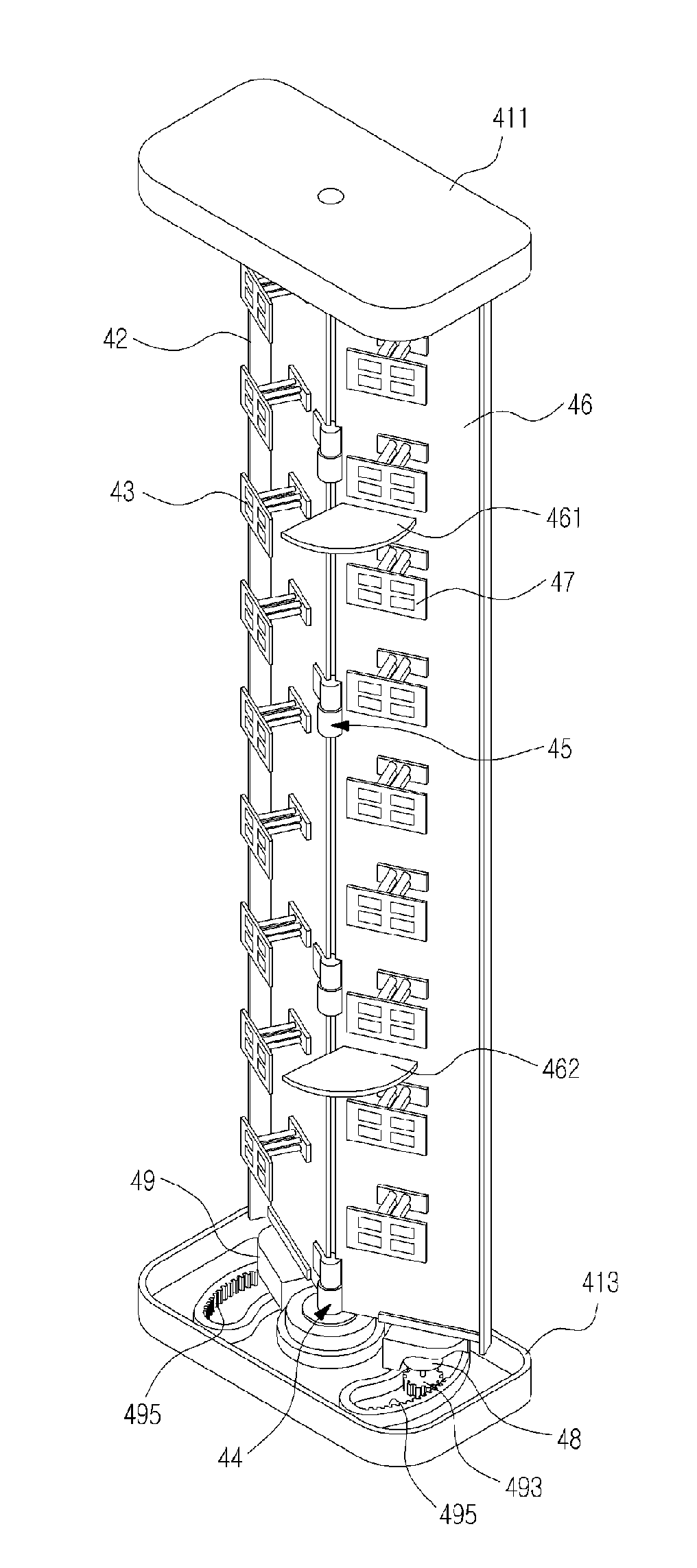
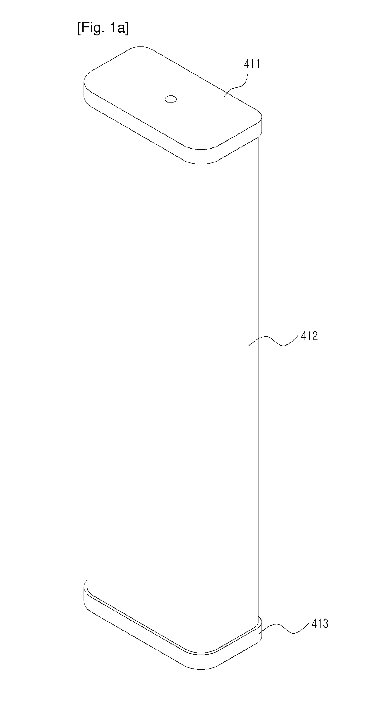
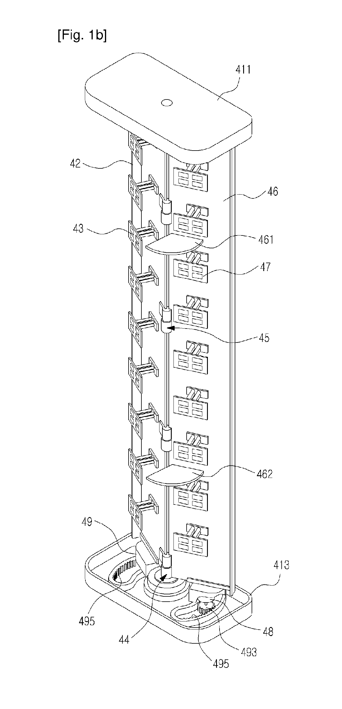
[0025]FIG. 1a is a perspective view of a base station according to the present invention, and FIG. 1b is a perspective view of the base station antenna shown in FIG. 1a, with its radome removed.

[0026]Referring to FIG. 1a, the base station antenna according to the first embodiment of the present invention has a contour defined by a radome 412, the upper and lower portions of which are covered by upper and lower caps 411 and 413, respectively.

[0027]Referring to FIG. 1b, inside the radome 412 are installed a plurality of radiation elements 43 and 47, a first reflection plate 42, a second reflection plate 46, and various types of equipment for retaining the plurality of radiation elements 43 and 47 and the first and second reflection plates 42 and 46. Specifically, a base station antenna according to an embodiment of the present invention has reflection plate connection members 44 and 45 for rotatably retaining the plurality of radiation elements 43 and 47 and the first and second refle...

second embodiment

[0049]FIG. 6 is a perspective view of a base station antenna according to the present invention, and FIGS. 7a to 7e illustrate exemplary beam patterns, which are radiated from the base station antenna shown in FIG. 6, and directions.

[0050]The base station antenna according to the second embodiment of the present invention has the same structure as the base station antenna according to the first embodiment, except for a difference in the number of reflection plates inside the radome 612 and the construction of equipment for rotation of the reflection plates.

[0051]To be specific, the base station antenna according to the second embodiment has three reflection plates, i.e. first, second, and third plates 62, 64, and 66 inside the radome 612. With the first reflection plate 62 at the center, the second and third reflection plates 64 and 66 are positioned on both sides, respectively, and are connected to the first reflection plate 62 through reflection plate connection members 68 and 69,...


PUM


Abstract

The invention relates to a base station antenna, that includes two or more reflector plates, each provided with a radiating element. The base station antenna also includes a reflector plate connecting member connected to each reflector plate for enabling the rotation of the reflector plates. The base station antenna also includes a reflector plate controller providing control signals for controlling the rotation and stoppage of the reflector plates.

Description

BACKGROUND OF THE INVENTION[0001]1. Field of the Invention[0002]The present invention relates to a base station antenna, and more particularly to a base station antenna supporting multiple antenna schemes.[0003]2. Description of the Related Art[0004]Development of mobile communication technology is followed by expectations that, even before the 3G (3rd Generation) networks are saturated, 4G (4th Generation) networks will be constructed widely. One of international standards representing the 4G networks, i.e. Mobile WiMAX or LTE (Long Term Evolution) communication scheme, applies various technologies to increase the transmission rate per frequency band, i.e. capacity (bps / Hz), and, for the purpose of the most effective capacity increase, applies multiple antenna technology referred to as MIMO (Multi-Input Multi-Output).[0005]The essentials of multiple antenna technology for base station antennas are based on baseband signal processing technology. However, the degree of capacity incre...

Claims


Application Information

Patent Timeline
IPC IPC(8): H01Q3/04
CPCH01Q1/246H01Q21/08H01Q3/06H01Q3/005H01Q3/02H01Q3/24
Inventor KIM, IN-HOLEE, JAE-JUNKIM, KEE-BUMYOO, CHANG-WOO
Owner KMW INC
Why Eureka
Try Eureka