

Milling cutter
- Summary
- Abstract
- Description
- Claims
- Application Information
AI Technical Summary
Benefits of technology
Problems solved by technology
Method used
Image

Examples
Embodiment Construction
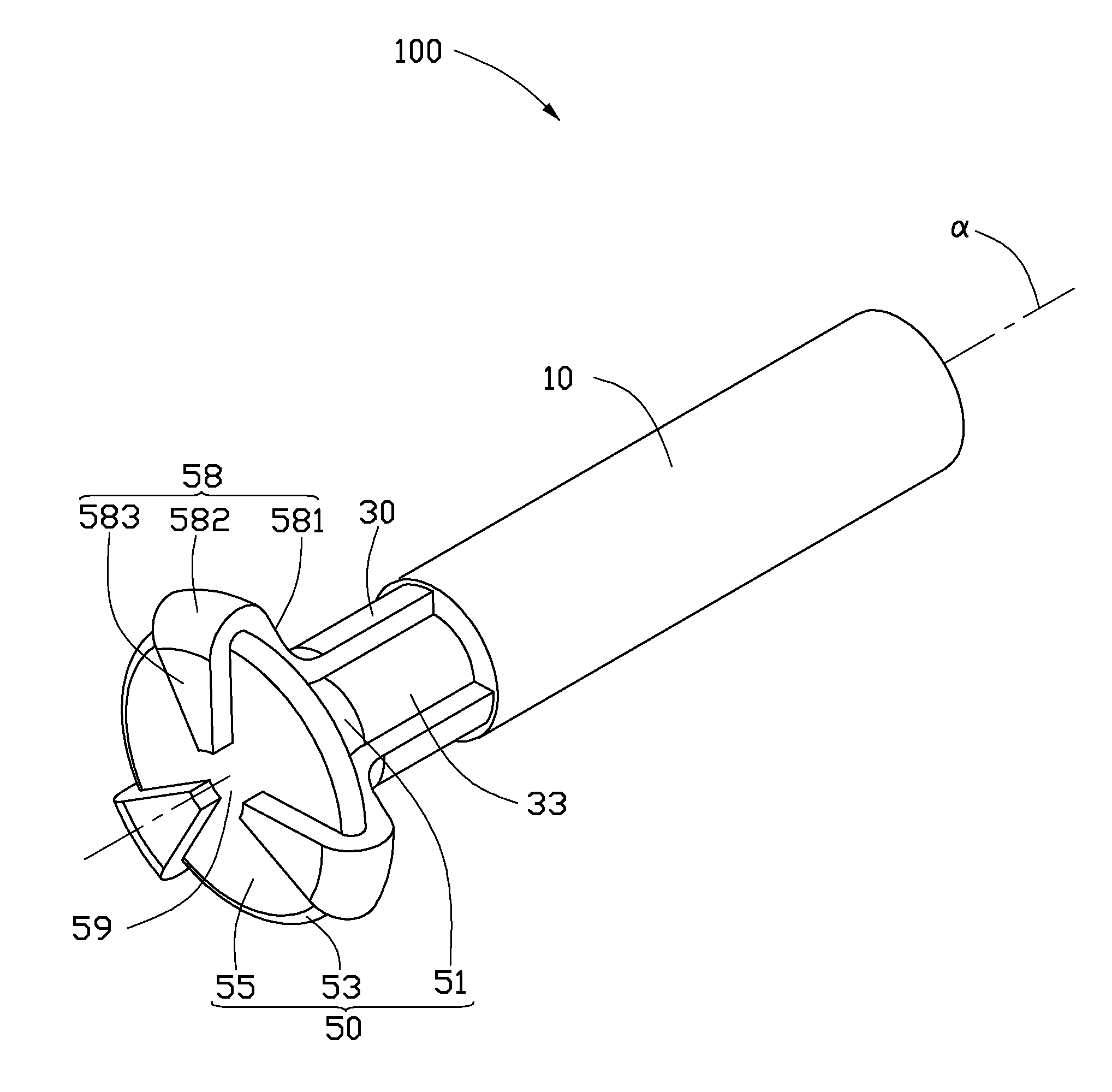
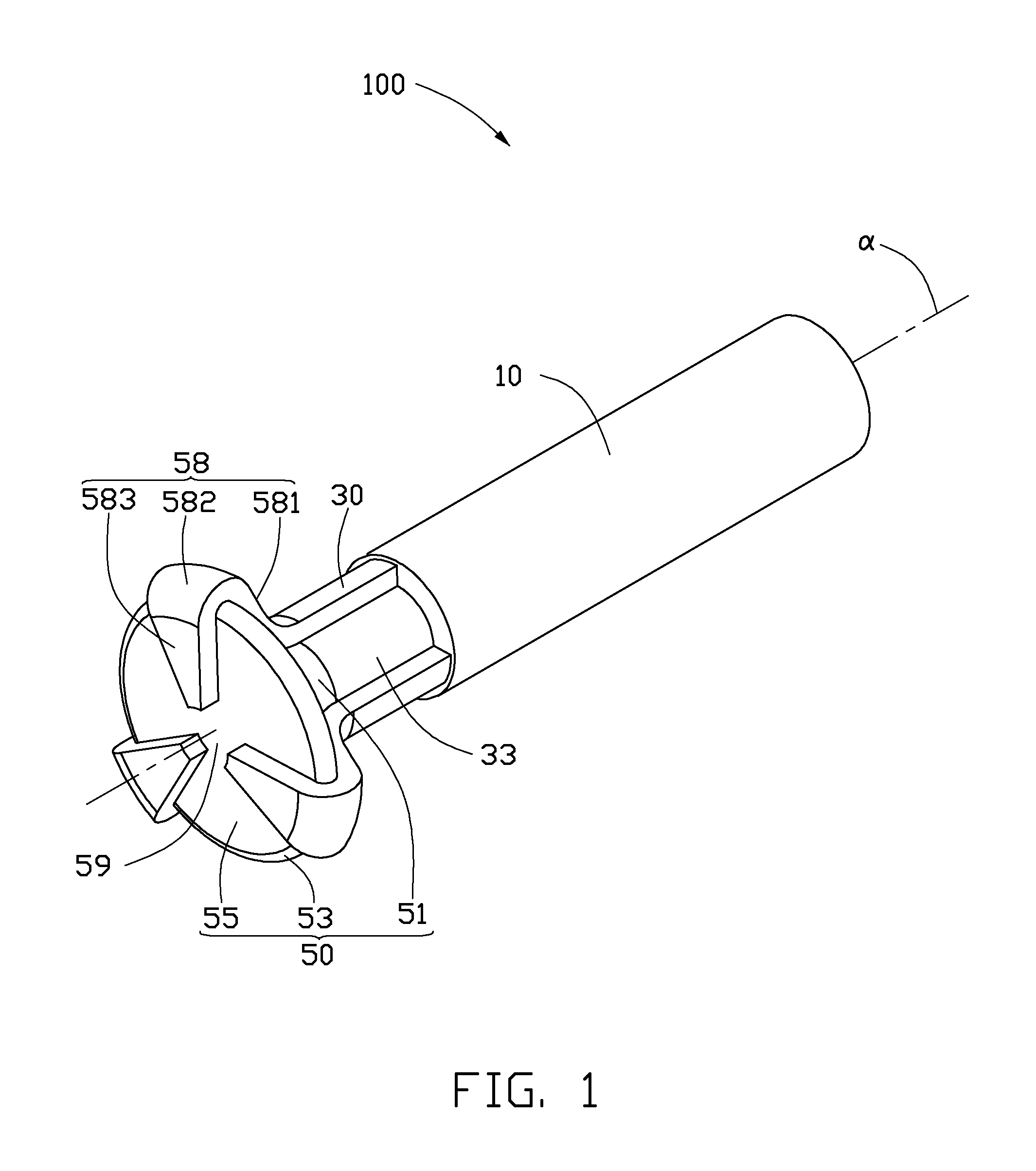
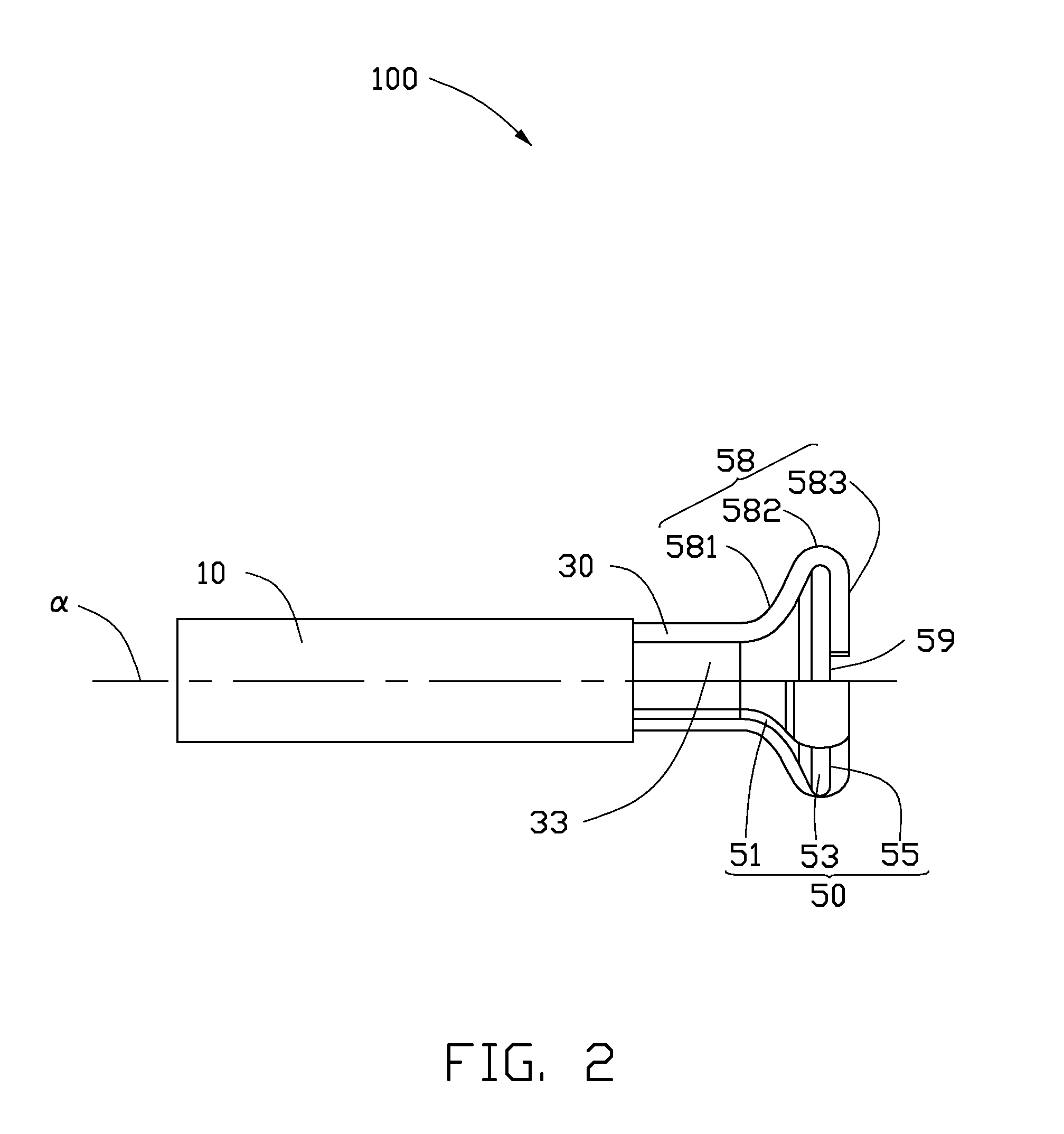
[0013]Referring to FIG. 1 and FIG. 2, an embodiment of a cutter 100 includes a cutter handle 10, a cutter neck 30, and a cutter head 50. The cutter neck 30 interconnects the cutter handle 10 and the cutter head 50.
[0014]Referring also to FIG. 3, a workpiece 200 which is desired to be fabricated to be a final product is presented. The workpiece 200 includes a curved surface 21, a flat surface 25, and a transitional surface 23 connecting the curved surface 21 and the flat surface 25.
[0015]In the illustrated embodiment, the cutter handle 10 can be a straight shank or a tapered shank. The cutter handle 10 is substantially cylindrical, and defines a center axis α. In machining, the cutter handle 10 rotates about the center axis a as a rotation axis. The cutter handle 10 is used for fixing the cutter 100 to a main shaft (not shown) of a numerical control machine (not shown), to maintain the stability of the cutter 100 during machining.
[0016]In the present embodiment, the cutter neck 30 is...
PUM
 Abstract
Description
Claims
Application Information