
Autonomous mobile device

a mobile device and autonomous technology, applied in the direction of process and machine control, distance measurement, instruments, etc., can solve the problem of not being able to detect the foregoing zones in which the autonomous mobile device enters

Active Publication Date: 2012-11-08
MURATA MASCH LTD
View PDF24 Cites 33 Cited by
  • Summary
  • Abstract
  • Description
  • Claims
  • Application Information

AI Technical Summary

Benefits of technology

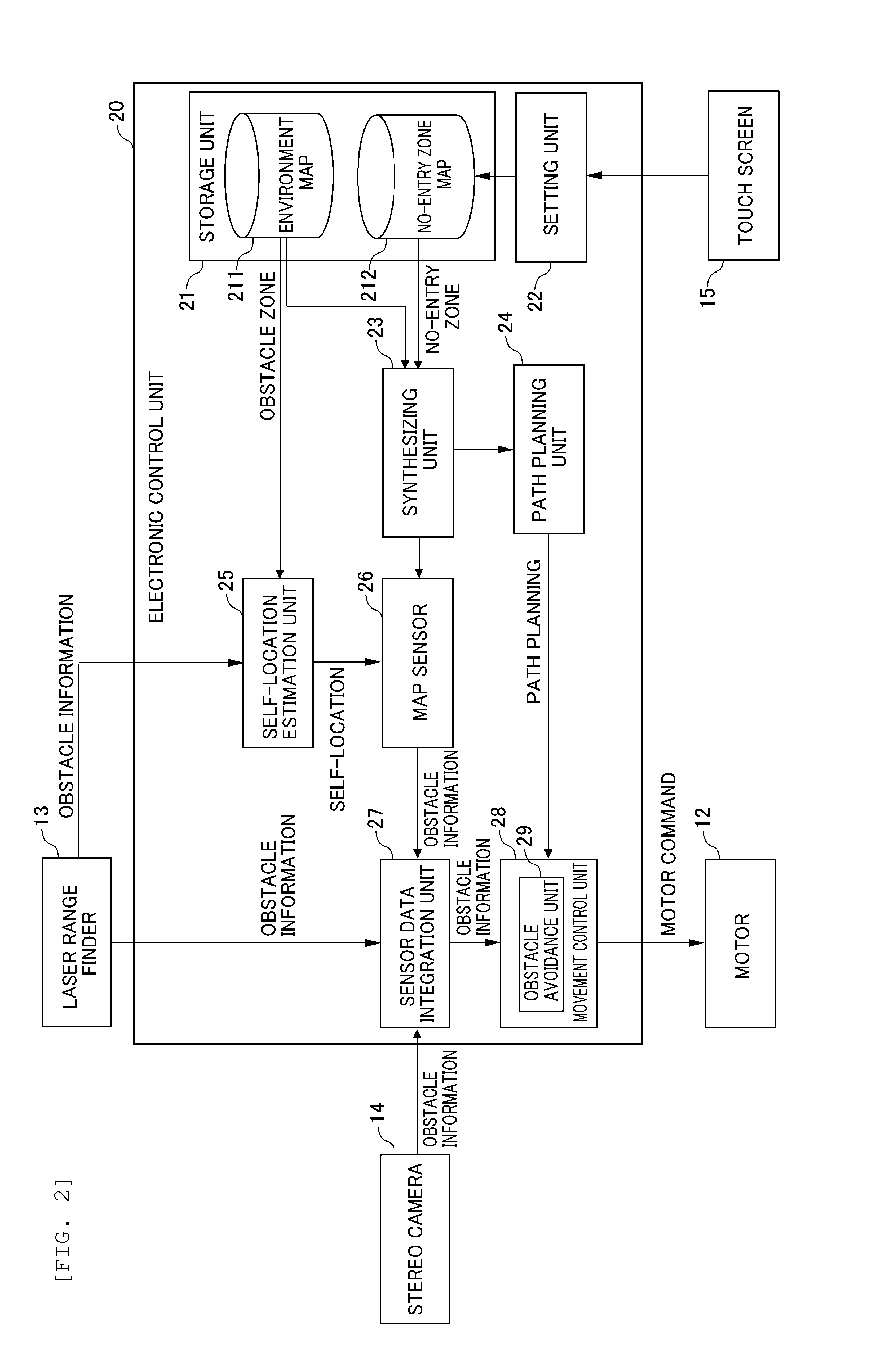
[0008]According to a preferred embodiment of the autonomous mobile device of the present invention, in addition to the environment map showing the obstacle zone, a no-entry zone map showing the no-entry zone into which entry of the autonomous mobile device is prohibited is also stored in the storage device. In addition, the self-location of the host device on the environment map is estimated by the estimation device based on the environment map and the acquired obstacle information. Consequently, the self-location of the host device on the environment map can be estimated without being affected by the no-entry zone based on the obstacle information acquired by the obstacle sensor and the environment map. Accordingly, it is possible to prevent errors in the estimation of the self-location. Moreover, the autonomous movement is controlled by the controller based on the estimated self-location, the environment map, and the no-entry zone map. The autonomous mobile device is thereby able to move while avoiding the obstacle zone and the no-entry zone and estimating the self-location. In other words, the autonomous mobile device can move while autonomously avoiding zones into which entry should be avoided even if no obstacle exists therein.
[0010]Preferably, the autonomous mobile device according to a preferred embodiment of the present invention preferably also includes a synthesizing device that generates a composite map by synthesizing the environment map and the no-entry zone map. Moreover, preferably, the synthesizing device generates the composite map which reflects both an obstacle zone shown on the environment map and a no-entry zone shown on the no-entry zone map for each of pixels corresponding mutually to the environment map and the no-entry zone map. Moreover, preferably, the autonomous mobile device also includes a planning device that plans a path to a destination by using the composite map generated by the synthesizing device, and the controller controls the autonomous movement based on the path planned by the planning device. In the foregoing case, since the planning device plans the path based on the composite map, it is possible to plan a path that avoids both the obstacle zone and the no-entry zone.
[0014]Preferably, the autonomous mobile device according to a preferred embodiment of the present invention also includes an integration device that integrates the obstacle information acquired by the obstacle sensor and the avoidance information calculated by the calculation device, and the controller performs control to avoid an obstacle by using the obstacle information and the avoidance information integrated by the integration device. In the foregoing case, even in cases where the number of obstacle sensors is changed, the integrated obstacle information is input to the controller and, therefore, the need to change software in the controller can be minimized.
[0016]According to various preferred embodiments of the present invention, the autonomous mobile device can move while autonomously avoiding zones into which entry should be avoided even if no obstacle exists therein.

Problems solved by technology

Nevertheless, with the autonomous mobile device described in Japanese Patent Application Publication No. 2005-157625, it is not possible to detect the foregoing zones into which entry by the autonomous mobile device should be avoided unless an obstacle exists therein.

Method used


Image

  • Autonomous mobile device
  • Autonomous mobile device
  • Autonomous mobile device

Examples


Embodiment Construction

[0030]The preferred embodiments of the present invention are now explained in detail with reference to the drawings.

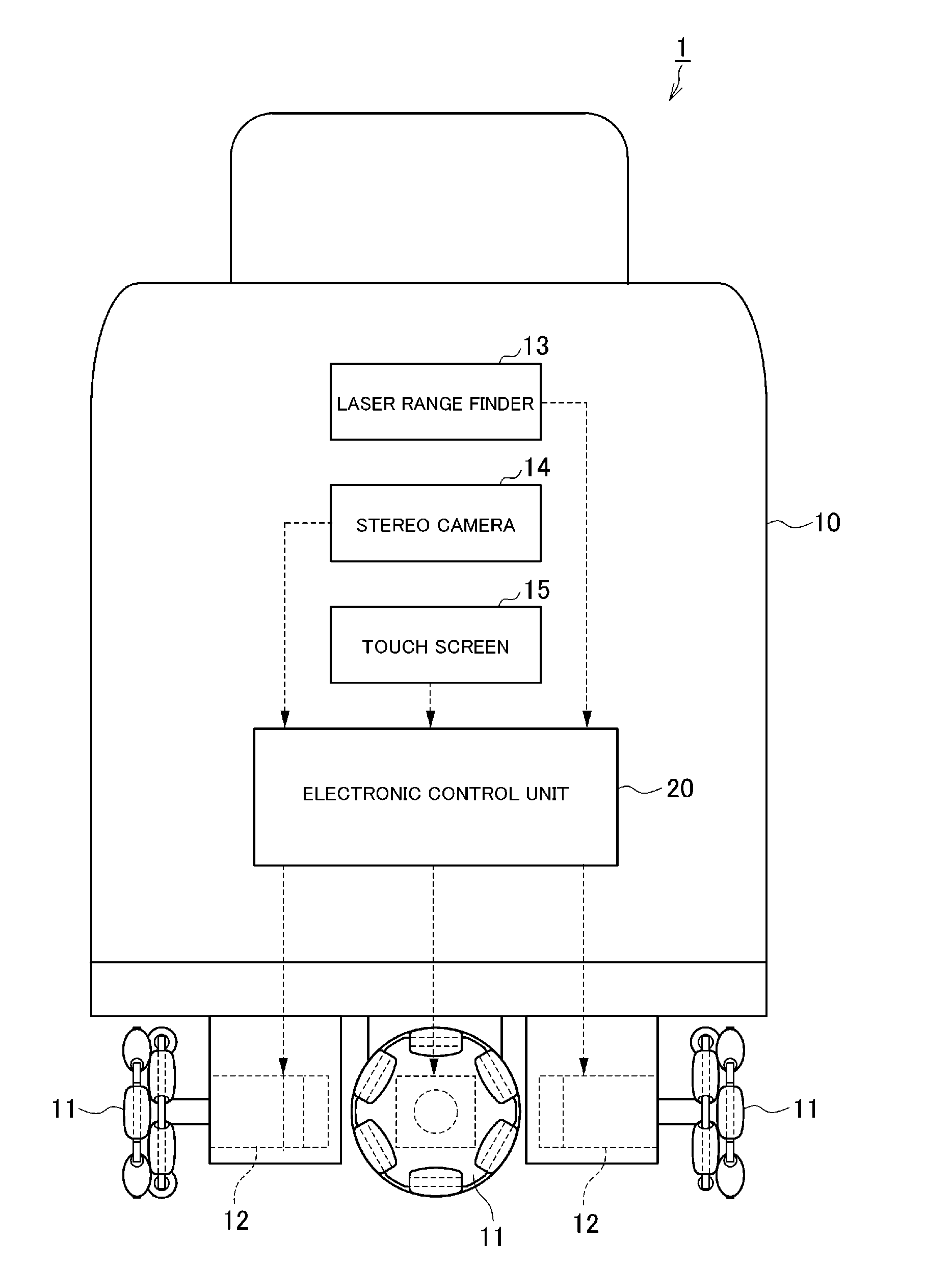
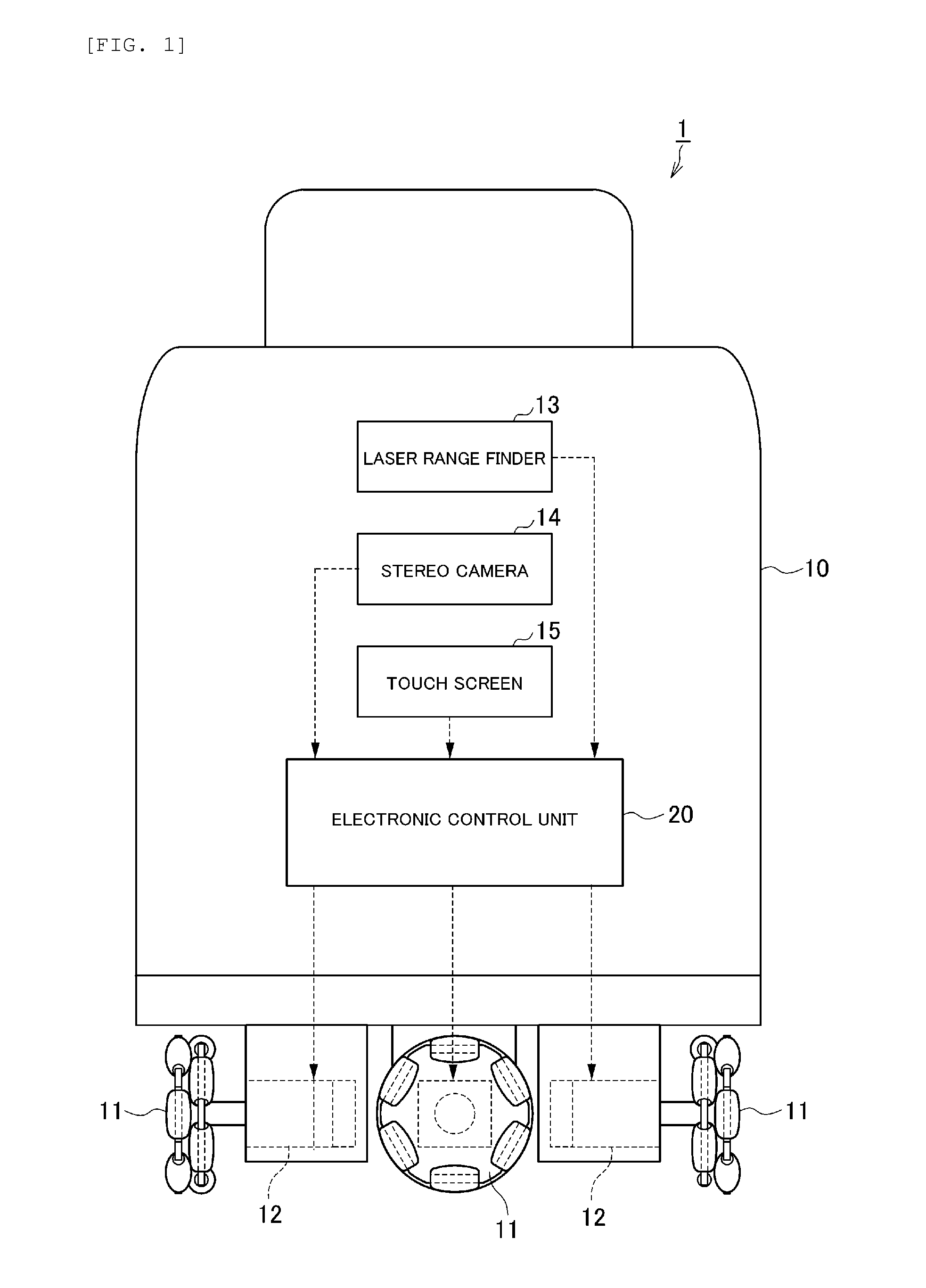
[0031]The configuration of the autonomous mobile device 1 according to the present preferred embodiment is foremost explained with reference to FIG. 1. FIG. 1 is a diagram explaining the configuration of the autonomous mobile device 1 according to the present preferred embodiment. The autonomous mobile device 1 is a device which autonomously moves to a destination while avoiding obstacles such as people and objects as well as the no-entry zones that are set.

[0032]The autonomous mobile device 1 preferably includes a hollow cylindrical main body 10 made of metal, four omni wheels 11 provided at the lower side of the main body 10, and four electric motors 12 that drive the omni wheels 11. The autonomous mobile device 1 can move in an arbitrary direction on the travel surface by individually adjusting the rotating direction and rotation speed of each of the four omni wheel...


PUM


Abstract

An autonomous mobile device that moves while autonomously avoiding zones into which entry should be avoided even if no obstacle exists therein includes a laser range finder that acquires peripheral obstacle information, a storage unit that stores an environment map that shows an obstacle zone where an obstacle exists, and a no-entry zone map which shows a no-entry zone into which entry is prohibited, a self-location estimation unit that estimates the self-location of a host device by using the obstacle information acquired by the laser range finder and the environment map, and a travel control unit that controls the host device to autonomously travel to the destination by avoiding the obstacle zone and the no-entry zone based on the estimated self-location, the environment map, and the no-entry zone map.

Description

BACKGROUND OF THE INVENTION[0001]1. Field of the Invention[0002]The present invention relates to an autonomous mobile device which autonomously moves to a destination.[0003]2. Description of the Related Art[0004]A conventional autonomous mobile device autonomously moves to a destination while avoiding obstacles by using map information showing the shape of obstacles such as walls, and a horizontal distance from a host device to the obstacle measured by a distance sensor (for instance, refer to Japanese Patent Application Publication No. 2005-157625).[0005]Meanwhile, zones into which the entry by the autonomous mobile device should be avoided are not necessarily limited to zones containing obstacles. For example, in an environment of a hospital or the like, as zones into which the entry by the autonomous mobile device should be avoided, there are stepped zones such as stairs where the autonomous mobile device is unable to travel and zones such as treatment rooms of patients that woul...

Claims


Application Information

Patent Timeline
Patent Type & Authority Applications(United States)
IPC IPC(8): G05D1/00
CPCG05D1/0214G05D1/024G05D1/0274G05D2201/0206Y10S901/46G09B29/10G05D1/0238Y10S901/01G09B29/007G09B29/00
Inventor NAKANO, TSUYOSHITANAKA, SHOJI
Owner MURATA MASCH LTD
Learn More