
Rotary die cutter insert

a rotary die cutter and insert technology, which is applied in the field of high-speed rotary die cutters, can solve the problems of insufficient scrap rejection assistance by rubber blocks, insufficient scrap elimination certainty, and inability to achieve the effect of scrap elimination and more control

Inactive Publication Date: 2012-11-15
WEIBELT BRUCE
View PDF11 Cites 45 Cited by
  • Summary
  • Abstract
  • Description
  • Claims
  • Application Information

AI Technical Summary

Benefits of technology

"The invention is a hardened insert used in rotary cutting dies to control the position and ejection of die cut scrap. The insert has ribs and grooves to limit instability and improve the ejection of scrap. It also helps to stabilize the cutting rule and reduce bending and flexing in the high-speed environment of the die cutter. The insert is positioned within the cutting rule area and is supported by the underlying material. The use of the insert reduces the likelihood of instability and improves the quality of the finished product."

Problems solved by technology

The use of rubber blocks is insufficient to assist scrap rejection in a high speed Rotary die cutting machine.
Even with finely tuned reactive structures assisting in the rejection of scrap, the certainty with which this scrap material is eliminated as soon as possible after it is cut from corrugated fiberboard sheet is not yet achieved.
Corrugated fiberboard sheet scrap may be unintentionally carried with the corrugated fiberboard sheet product to a stacking machine downstream from the operation of the anvil cylinder and blanking die roll.
The second, and traditionally less controllable way that scrap can make it into the finished product is by failure of the scrap to be rejected from within the cutting rule.
The presence of scrap within cut cardboard is costly and hazardous.
Where the presence of scrap is prominent enough to cause the producer of the cut cardboard to visually notice it, it results in additional handling, and more personnel than would otherwise be needed.
Where the scrap is present in the die cut and stacked cardboard, it disrupts further handling machinery.
One small piece of scrap can prevent vacuum engagement and cause a machine to jam.
The most expensive and highest speed processing types of machinery have a higher reliance upon a consistent product feed stock which can be engaged consistently at high speed and speedily manipulated.
The presence of scrap within cut cardboard can result in high numbers of ruined constructed structures or can cause the machinery to shut down until repaired.
Where capacity of final production machinery is high, even a 10 minute shut down can result in significant loss of production.
A thirty second malfunction can ruin high numbers of products resulting a significant waste.
Corrugated fiberboard sheet scrap may therefore eventually wind up within the corrugated fiberboard sheet product, carton, box or processed the like formed in the die cutting operation.
Unwanted scrap downstream of the die cutting process can have very undesirable consequences, particularly when the carton or box is used for foods, such as pizza, which can be contaminated by the scrap paperboard.
Scrap contamination of the carton or box can also ensue when the blocks of product ejection rubber do not extend rapidly enough, as they exit from space between the die roll and anvil cylinder of the apparatus, to prevent the paperboard stock from advancing beneath the trimmed scrap, and then being transported by the cut paperboard stock to the packing machine.
Doubling can cause scrap to be transmitted to the final product by forming an incomplete cut.
An incomplete cut can cause a “shad” effect and draw scrap into the finished product.
Doubling can also cause scrap to remain within the blade area over several cutting cycles.

Method used


Image

  • Rotary die cutter insert
  • Rotary die cutter insert
  • Rotary die cutter insert

Examples


Embodiment Construction

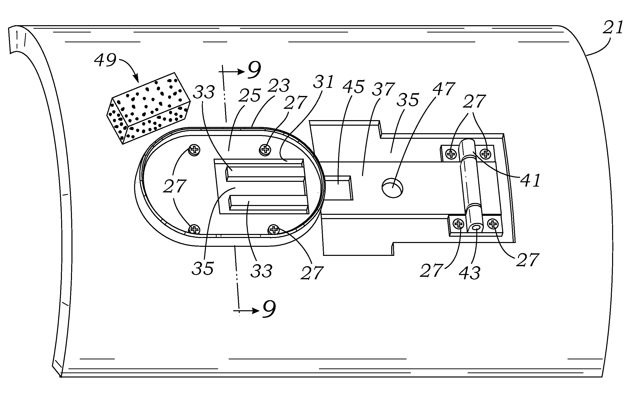
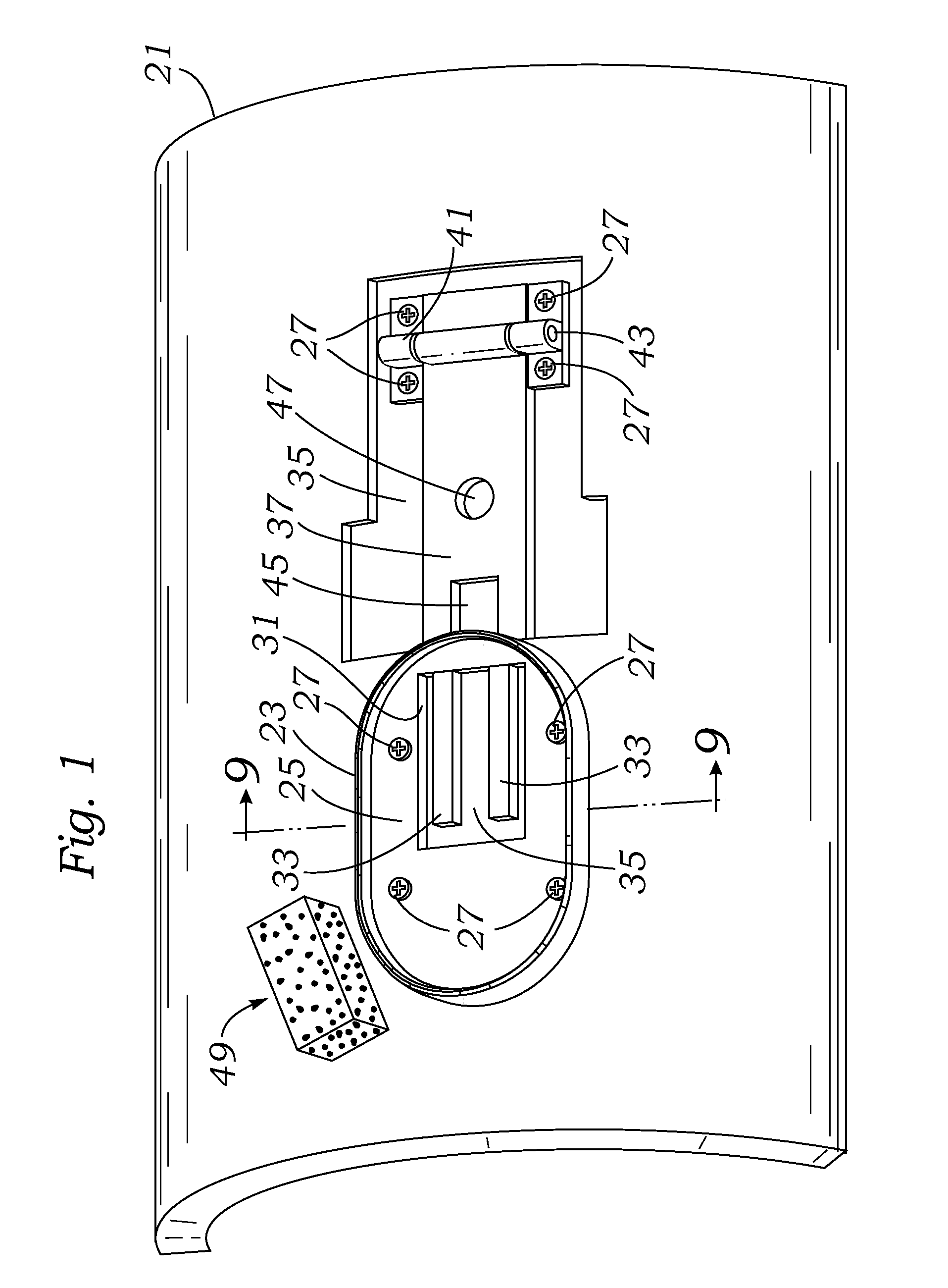
[0032]Referring to FIG. 1, a perspective view of but one configuration of the use of the insert of the invention is illustrated. Within a curved blanking die roll section 21 which is made of a thickness of material, such as wood, polymer, fiber board or the equivalent. Curved blanking die roll section 21 may be of the type to fit onto a curved cutting die panel drum of a high speed Mitsubishi Evol rotary die cutter (not shown) and will turn opposite an anvil drum (also not shown). The view of FIG. 1 is an outside view of the curved blanking die roll section 21 showing the mounting of a die cutting rule 23 which may be a mounted in and carried by a thin laser formed slot in the curved blanking die roll section 21. The shape of the mounting of a die cutting rule 23 shown in FIG. 1 is that of an elongated circle or racetrack shape, typically used to cut box hand holds to facilitate grasping and carrying of a box manually from the outside.

[0033]Just inside the inner periphery of die cut...


PUM

PropertyMeasurementUnit
diameteraaaaaaaaaa
diameteraaaaaaaaaa
diameteraaaaaaaaaa

Abstract

The provision of a hardened elevated surface within the a inside die cutting area of a cutting rule to limit and control the extent to which die cut scrap processed corrugated fiberboard sheet material can position itself within the area within the cutting rule before ejection limit the tendency for instability within the cutting rule after the die cut is achieved and to better control the ejection of the scrap processed corrugated fiberboard sheet material to better eliminate unwanted scrap downstream of the die cutting process. Eliminated scrap reduces malfunctions in further processing and helps to eliminate health and contamination hazards in the finished corrugated fiberboard sheet product.

Description

[0001]This is a continuation of co-pending Provisional Patent No. 61 / 484,837 filed May 11, 2011.FIELD OF THE INVENTION[0002]The present invention relates to improvements in the field of high speed rotary die cutters especially for use in cutting corrugated paperboard such as is used in paper products such as boxes, and more specifically, but not limited to use in the high speed Mitsubishi EVOL die cutter to enhance the ability to control scrap separation to enhance the probability of producing a scrap-free product.BACKGROUND OF THE INVENTION[0003]Rotary die cutting machines (not shown in the drawings) have been publicly known. In these types of cutters a frame is used to provide powered rotation to a die cut cylinder and an anvil cylinder. A blanking die, which may be provided in sections, is attached to the die cut cylinder to form a blanking die roll and rotated together with the anvil cylinder. The rotary die cutting machine is commonly used in the manufacture of cartons or boxes...

Claims


Application Information

Patent Timeline
Patent Type & Authority Applications(United States)
IPC IPC(8): B26D7/18B26F1/44B26D1/14
CPCB26D7/1818B26F1/44B26D2007/2607Y10T83/2107Y10T83/4795Y10T83/2037Y10T83/2109Y10T83/2122
Inventor WEIBELT, BRUCE
Owner WEIBELT BRUCE
Learn More