
Nanostructured composite polymer thermal/electrical interface material and method for making the same

a composite polymer and thermal/electrical interface technology, applied in the field of thermal transfer systems, can solve the problems of limiting the temperature available to drive heat rejection from convective surfaces, loss of more than 10-20° c. across each interface, and conventional tims have failed to address such desires

Inactive Publication Date: 2012-11-15
GEORGIA TECH RES CORP
View PDF4 Cites 27 Cited by
  • Summary
  • Abstract
  • Description
  • Claims
  • Application Information

AI Technical Summary

Benefits of technology

The present invention relates to thermal interface materials used to transfer heat between a heat source and a heat sink. The material is made up of a plurality of polymer nanofibers that are aligned perpendicular to the heat source and heat sink. The nanofibers can be conductive, semiconductor, or insulative. The material has low thermal resistance and can be used in a heat transfer system. The technical effect of the invention is to provide a more efficient and effective thermal interface material for improving heat transfer between the heat source and heat sink.

Problems solved by technology

With the power density of chips projected to exceed 100 W / cm2 in the near future, the use of some of the best conventional TIMs would still result in a loss of more than 10-20° C. across each interface in a packaged device, severely limiting the temperature available to drive heat rejection from convective surfaces.
Conventional TIMs have failed to address such desires.
While CNTs appear attractive at first due to their high thermal conductivity, the poor contact between CNTs and substrate presents a major bottleneck to thermal transport.
These systems, however, suffer from choosing between adhesion and mechanical compliance.
For example, while polymer-based TIMs have shown significant advancements over prior TIMs, conventional polymer-based TIMs are still limited by the low thermal conductivity of bulk polymers.
Such approaches, however, compromises other properties such as mechanical compliance.
Furthermore, the obtained thermal conductivity is lower than the theoretically predicted thermal conductivity because of unfavorable phonon dynamics caused by increased material interfaces and large mismatches in properties of the filler material and polymer matrix.

Method used


Image

  • Nanostructured composite polymer thermal/electrical interface material and method for making the same
  • Nanostructured composite polymer thermal/electrical interface material and method for making the same
  • Nanostructured composite polymer thermal/electrical interface material and method for making the same

Examples


Embodiment Construction

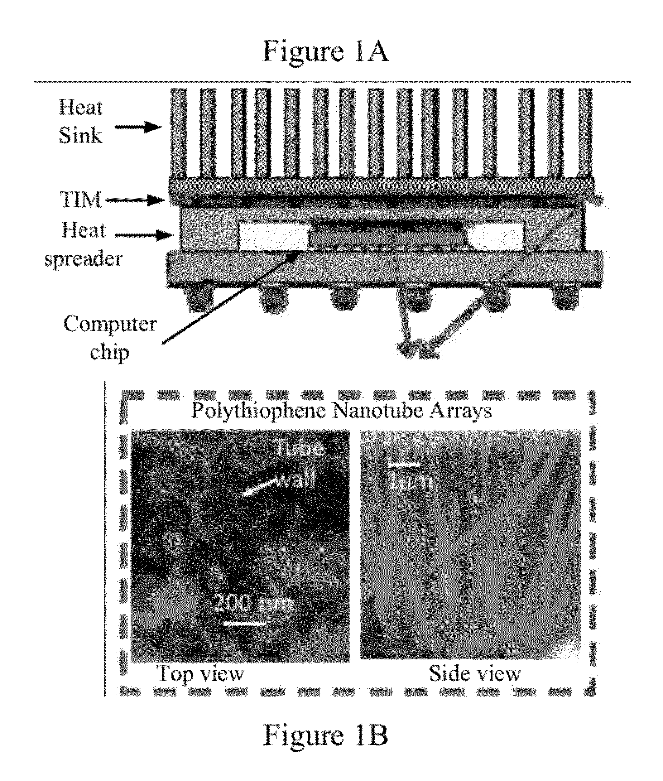
[0030]To facilitate an understanding of the principles and features of the present invention, various illustrative embodiments are explained below. In particular, the invention is described in the context of being thermal interface materials, heat transfer systems, and methods of fabricating thermal interface materials. Embodiments of the present invention may be applied to many systems or devices where it is desired to transfer thermal energy from a heat source to a heat sink, including, but not limited to, electronic chip stacks.

[0031]The components described hereinafter as making up various elements of the invention are intended to be illustrative and not restrictive. Many suitable components or steps that would perform the same or similar functions as the components or steps described herein are intended to be embraced within the scope of the invention. Such other components or steps not described herein can include, but are not limited to, for example, similar components or ste...


PUM

PropertyMeasurementUnit
temperatureaaaaaaaaaa
interface pressureaaaaaaaaaa
timeaaaaaaaaaa

Abstract

An exemplary embodiment of the present invention provides a thermal interface material for providing thermal communication between a heat sink and a heat source. The thermal interface material comprises a plurality of polymer nanofibers having first ends and second ends. The first ends can be positioned substantially adjacent to the heat source. The second ends can be positioned substantially adjacent to the heat sink. The plurality of polymer nanofibers can be aligned substantially perpendicular to at least a portion of the heat source and the heat sink.

Description

CROSS-REFERENCE TO RELATED APPLICATIONS[0001]This application claims the benefit of U.S. Provisional Application Ser. No. 61 / 484,937, filed on 11 May 2011, which is incorporated herein by reference in its entirety as if fully set forth below.TECHNICAL FIELD OF THE INVENTION[0002]The various embodiments of the present disclosure relate generally to thermal transfer systems. More particularly, the various embodiments of the present invention are directed to nanostructured polymer based thermal interface materials.BACKGROUND OF THE INVENTION[0003]Thermal interface materials (“TIMs”) are used in many systems where it is desirable to transfer heat from a heat source to a heat sink. For example, in a three-dimensional stack of microchips, it is often desirable to transfer heat generated by a chip to a heat sink in order to cool the chip. Heat can be transferred via a TIM located between the heat source and the heat sink. Thus, thermal energy located in the heat source travels through the ...

Claims


Application Information

Patent Timeline
Patent Type & Authority Applications(United States)
IPC IPC(8): F28F7/00B32B5/16B82Y30/00
CPCB82Y30/00Y10T428/24174H01L2224/32245H01L2224/73253H01L2924/15311H01L2924/16251H01L23/3737D01D5/00D01D5/24D01F1/10D01F6/74H01L2224/16227H01L2224/32225H01L2224/73204H01L2224/16225H01L2924/00H01L2924/00014Y02P70/62H01L2224/0401
Inventor COLA, BARATUNDE A.KALAITZIDOU, KYRIAKISANTOSO, HANDOKO T.SINGH, VIRENDRA
Owner GEORGIA TECH RES CORP
Learn More