Inspection Device Applying Probe Contact for Signal Transmission

a technology of signal transmission and probe contact, which is applied in the direction of measurement devices, substation equipment, instruments, etc., can solve the problems of easy scratching of the housing of the inspected electronic product by the worn-out guiding rail, the off position of the probe, and the inability to carry out further inspection, so as to save the procedure of installing the power supply battery and enhance the inspection efficiency. , the effect of enhancing the contact quality

Inactive Publication Date: 2012-11-15
ASKEY COMP
View PDF15 Cites 15 Cited by
  • Summary
  • Abstract
  • Description
  • Claims
  • Application Information

AI Technical Summary

Benefits of technology

[0011]According to the stated aforesaid, the inspection device applying probe contact for signal transmission of the present invention is capable of steadily positioning the inspected portable electronic apparatus, as well enhancing contact quality between the probes and the portable electronic apparatus, also the power supply open chamber disposed on the fillister for containing the power supply module provides advantage of saving the procedure of installing power supply battery for inspected portable electronic apparatus, thereby greatly enhancing inspection efficiency. In addition, by using said POM and PTFE materials, avoiding the risk of scratching the housing of the portable electronic apparatus.

Problems solved by technology

Consequently, not only the inspected portable electronic apparatus cannot be positioned properly in the receiving mount 1, but also the plurality of probes 10 cannot be smoothly plugged in the signal terminals of the portable electronic apparatus, thereby causing the probes off position and further inspection error as well.
Besides, the housing of the inspected electronic product is easily scratched by the worn-out guiding rails 11.

Method used


Image

  • Inspection Device Applying Probe Contact for Signal Transmission
  • Inspection Device Applying Probe Contact for Signal Transmission
  • Inspection Device Applying Probe Contact for Signal Transmission

Examples


Embodiment Construction

[0018]The following illustrative embodiments are provided to illustrate the disclosure of the present invention; those in the art can apparently understand these and other advantages and effects after reading the disclosure of this specification. The present invention can also be performed or applied by other different embodiments. The details of the specification may be on the basis of different points and applications, and numerous modifications and variations can be devised without departing from the spirit of the present invention.

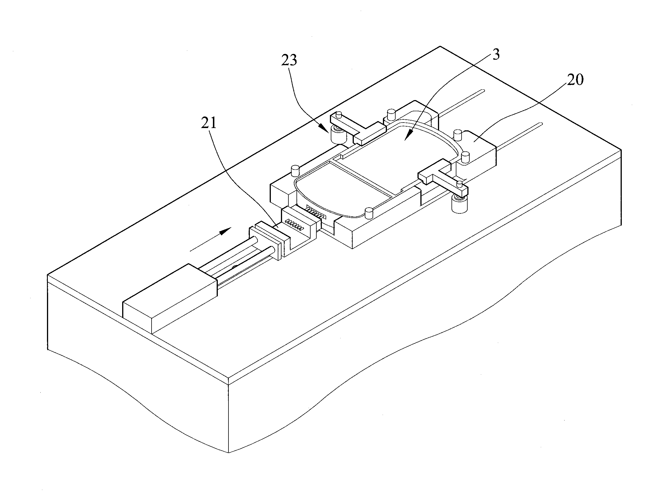
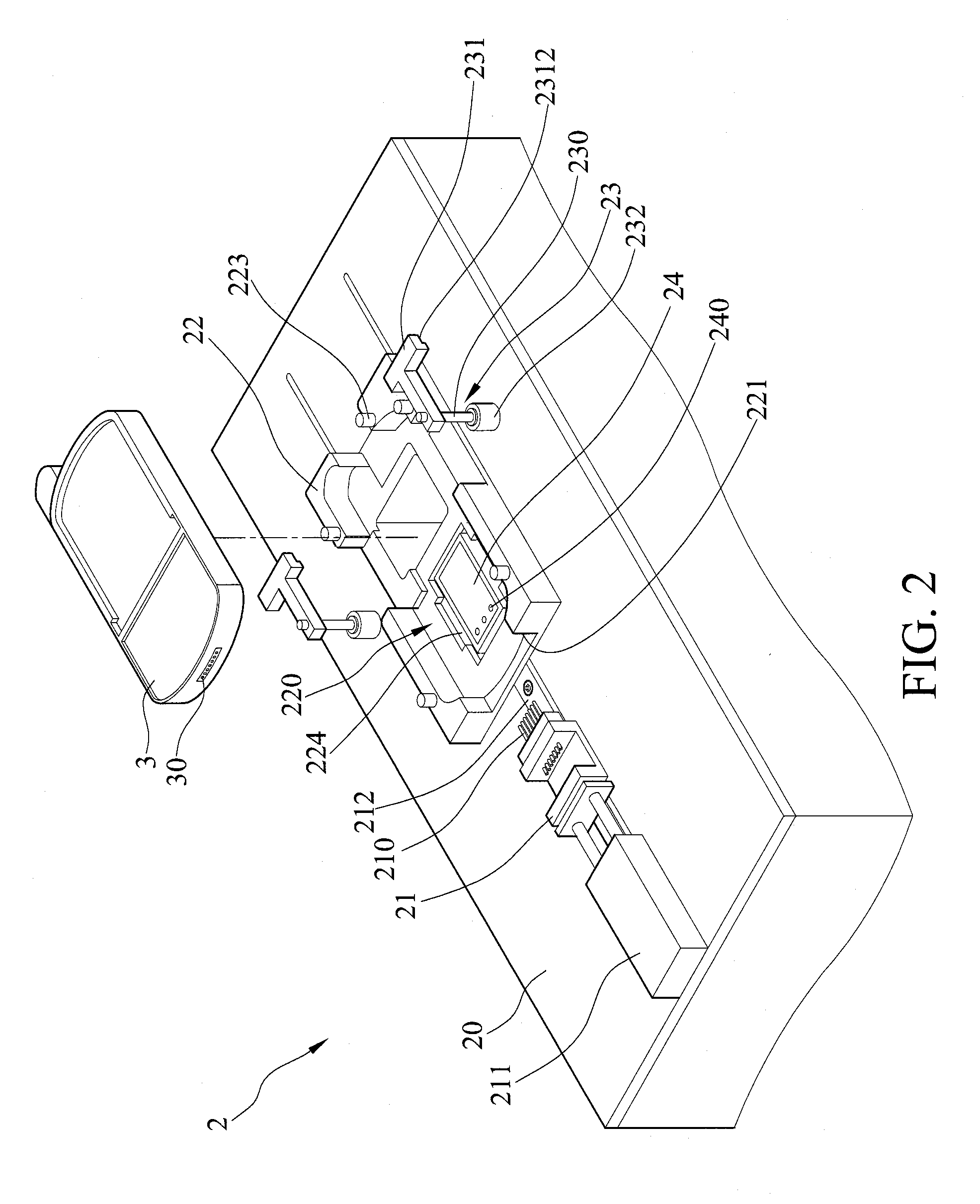
[0019]Please refer to FIG. 2, which is an exterior view of an inspection device applying probe contact for signal transmission according to the present invention.

[0020]The inspection device 2 applying probe contact for signal transmission of the present invention is for processing function inspection on an inspected portable electronic apparatus 3. The inspection device 2 comprises an inspection panel board 20, a probe base 21, a receiving moldboard 22...


PUM


Abstract

An inspection device applying probe contact for signal transmission includes an inspection panel board; a probe base disposed on the inspection panel board and having a plurality of probes; a receiving moldboard disposed on the inspection panel board and including a fillister for receiving inspected portable electronic apparatus, and an open slot allocated facing the plurality of probes of the probe base, thereby enabling the plurality of probes to contact with corresponding signal terminals of the portable electronic apparatus; and a clamp unit disposed on the inspection panel board and consisting of an adjustable rod and a clamp block allocated at one end of the adjustable rod, the adjustable rod adjusting position of the clamp block, thereby clamping and properly positioning the portable electronic apparatus in the receiving moldboard.

Description

BACKGROUND OF THE INVENTION[0001]1. Field of the Invention[0002]This invention relates to inspection devices, and, more particularly, to an inspection device applying probe contact for signal transmission.[0003]2. Description of Related Art[0004]In a mass production of or before putting portable electronic apparatus in the market, a quality inspection procedure is generally taken to ensure the merchandise quality.[0005]As shown in FIG. 1, which is a partial exterior view of a traditional inspection device for portable electronic apparatuses. The main body of the inspection device has a receiving mount 1 and a plurality of probes 10 disposed on one end side of the receiving mount 1. Guiding rails 11 are disposed at each of the opposing lateral sides of the receiving mount 1. The inspected portable electronic apparatus is guided by the guiding rails 11 and then positioned steadily in the receiving mount 1. The plurality of probes are enabled to be plug in the signal terminals of the p...

Claims


Application Information

Patent Timeline
Patent Type & Authority Applications(United States)
IPC IPC(8): G01R1/067
CPCG01R1/0408H04M1/04H04M1/24
Inventor CHEN, CHIAN-JUNGHSIEH, CHING-FENG
Owner ASKEY COMP
Why Eureka
Try Eureka