

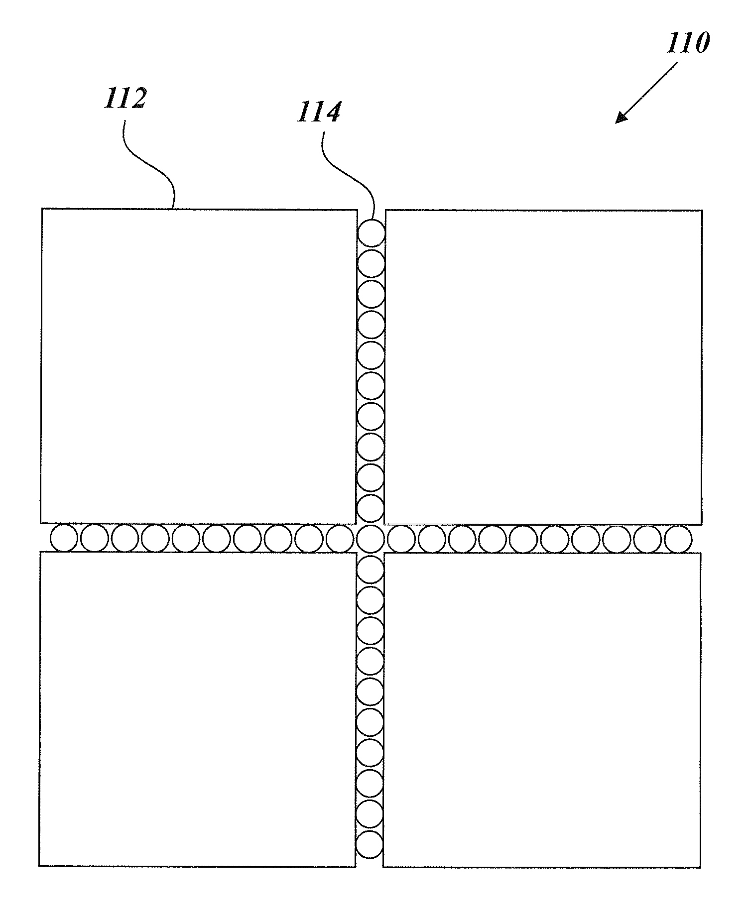
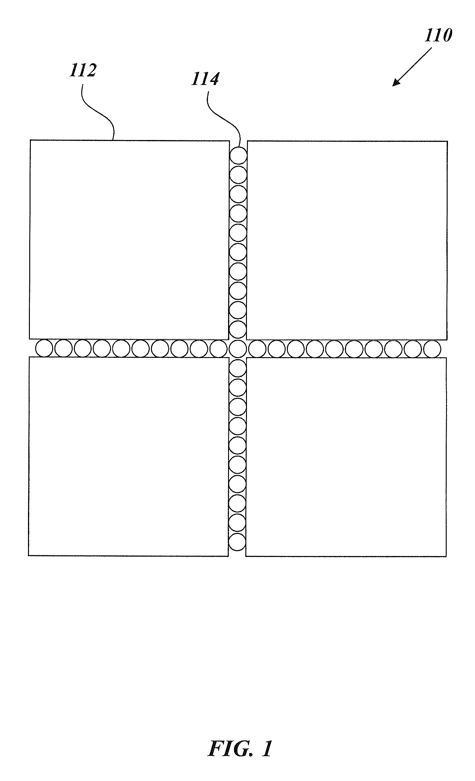
Magnetic grain boundary engineered ferrite core materials
a technology of ferrite core and magnetic grain boundary, which is applied in the field of composite materials having nanostructured magnetic grain boundary materials, can solve the problems of limiting the associated losses, limiting the maximum switching frequency, and often failing to provide cores capable of operating at extremely high frequencies, so as to achieve the effect of better satisfying the requirements
- Summary
- Abstract
- Description
- Claims
- Application Information
AI Technical Summary
Benefits of technology
Problems solved by technology
Method used
Image

Examples
examples i-iii
[0068]FIG. 10 depicts SEM images of the three example embodiments of sintered ferrite cores according to the present invention. As depicted by the visible boundary borders, the microstructures consist of MnZn ferrite grains surrounded by nano-scaled NiZn ferrite particles / clusters. The top image of FIG. 10 depicts Example I (herein referred to as B40N2), which possesses a distribution of 2 wt-% of NiZn particles. The middle image of FIG. 10 depicts Example II (herein referred to as B40N5), which possesses a distribution of 5 wt-% of NiZn particles. The bottom image of FIG. 10 depicts Example III (herein referred to as B40N7), which possesses a distribution of 7 wt-% of NiZn particles.
[0069]The composite materials of examples I-III were manufactured according to techniques described herein. Subsequent to manufacturing the materials, Energy Dispersive X-ray Spectroscopy (EDX) was also performed on Examples I-III. The fine particles on grains were found to be enriched in Ni, which conf...
PUM
| Property | Measurement | Unit |
|---|---|---|
| magnetic flux density | aaaaa | aaaaa |
| frequencies | aaaaa | aaaaa |
| frequencies | aaaaa | aaaaa |
Abstract
Description
Claims
Application Information