Magnetic Material and Method for Producing Same

a technology of magnetic materials and materials, applied in the field of magnetic materials, can solve the problems of deterioration of magnetic properties, increased cost of punching and lamination steps, and increased cost of punching and lamination steps, and achieves high saturation magnetization, small eddy current loss, and high oxidation resistance.

Active Publication Date: 2020-08-20
NAT INST OF ADVANCED IND SCI & TECH
View PDF2 Cites 6 Cited by
  • Summary
  • Abstract
  • Description
  • Claims
  • Application Information

AI Technical Summary

Benefits of technology

[0038]According to the present invention, there can be provided a magnetic material having a high saturation magnetization and a small eddy current loss, in particular a soft magnetic material that is suitably used even in high rotation motors and the like, and various soft magnetic materials and semi-hard magnetic materials having high oxidation resistance.
[0039]According to the present invention, because the magnetic material can be used in the form of a powder material like ferrite, it can easily be produced in bulk by sintering or the like, and hence the present invention can solve problems such as complicated steps like lamination and the like caused by the use of metallic soft magnetic materials known as thin sheets, as well as the high costs involved with such steps.

Problems solved by technology

Global environmental problems, such as global warming and exhaustion of resources, are becoming more severe, and the social demands for energy saving and using less resources in various electronic and electric devices are increasing day by day.
Therefore, the costs of the punching and lamination steps, and deterioration of the magnetic properties are serious problems.
However, the saturation magnetization is about 1 T, which is not large enough for next-generation automobiles.
The sendust is hard and brittle so that workability is poor, but has excellent wear resistance, and hence the sendust has been developed for applications such as magnetic heads utilizing such properties.
The electric resistivity is 0.8 μΩm, which is higher than other rolled metal materials, but it is not yet large enough for the next-generation automobiles.
However, the saturation magnetization has a value close to that of iron since the material itself is almost pure iron, but the electric resistivity is as low as 0.1 to 0.2 μΩm, and an eddy current loss increases in high rotation applications.
In addition, the coercive force is relatively high, namely, 12 to 240 A / m, and not only the eddy current loss but also an iron loss due to a hysteresis loss is hardly ignorable, particularly, in a motor at a low rotation speed.
Furthermore, the steel is soft and easily rusted, and thus, is inferior in cutting workability and oxidation resistance, and there is also a problem that magnetic properties are likely to change with time.
However, this material has a relatively low saturation magnetization, namely, 0.55 to 1.55 T, and there is a trade-off between the magnetization and the coercive force, and thus, it is difficult to obtain the material capable of simultaneously realizing the high magnetization and the low coercive force, and there is a problem that this material cannot be used for high-performance motors.
Furthermore, the electric resistivity is as small as 0.45 to 0.75 μΩm, and there is also a problem that the eddy current loss increases in high-rotation applications.
However, the saturation magnetization is 0.5 to 1.6 T, and particularly 0.6 to 0.8 Tin the material with the composition where the coercive force is 1 A / m or less, which is insufficient for use in high-performance motors.
Further, the electric resistivity is 1.2 to 1.4 μΩm, which is somewhat higher than crystalline soft magnetic materials such as a silicon steel sheet and permalloy, but there is a problem that the eddy current loss increases.
Further, insulation, cutting, alignment, lamination, welding, and annealing steps are more complicated than those with silicon steel, and the amorphous alloy becomes easily brittle due to heat and stress, and has poor workability.
Thus, there is also a problem that magnetic characteristics deteriorate and cost increases when being applied to high-rotation motors or the like.
However, this material is also produced as a thin ribbon by liquid rapid quenching as is the case with amorphous materials, and thus the thickness of the product is about 0.02 to 0.025 mm, and hence this material has the same problems as amorphous materials in terms of the steps, processability, eddy current loss, and increase in costs.
Furthermore, the electric resistivity is small at 1.2 μΩm, and a problem with the eddy current loss similar to other rolled materials and ribbons has been pointed out.
However, the magnetic properties are much worse than for a 0.02 mm ribbon, with a coercive force of 300 A / m and a saturation magnetization of 1 T. At present, there is no good method other than a lamination method for producing products thicker than 0.5 mm.
However, the coercive force of this material is comparatively high, namely, 2 to 160 A / m, and in particular, the saturation magnetization is small at 0.3 to 0.5 T. Therefore, this material is not suitable for high-performance, high-speed motors for next-generation automobiles, for example.
In general, metallic soft magnetic materials such as silicon steel have a low electric resistance, and suffer from the occurrence of eddy current loss for high-rotation, high-performance motors.
This results in serious problems such as the steps becoming complicated, magnetic properties deteriorating due to an insulation treatment before lamination, punching, and the like, and increased costs for the steps.
On the other hand, oxide-based soft magnetic materials such as ferrite have a large electric resistance and no problems with eddy current loss, but they are unsuitable for high-performance motors for next-generation automobiles because they have a small saturation magnetization of 0.5 T or less.
The steps of insulating, punching, aligning, welding, and annealing such a thin sheet are complicated and expensive.

Method used


Image

  • Magnetic Material and Method for Producing Same
  • Magnetic Material and Method for Producing Same

Examples


example 11

[0289]Aqueous solutions of MnCl2.4H2O (manganese(II) chloride tetrahydrate), an aqueous solution of CoCl2.6H2O (cobalt (II) chloride hexahydrate), and an aqueous solution of FeCl2.4H2O (iron (II) chloride tetrahydrate) were separately prepared, and a mixed aqueous solution of MnCl2, CoCl2, and FeCl2, obtained by mixing these solutions and adjusted to 50.3 mM, was placed in a reactor as a reaction field solution. It is noted that compositions of cobalt and manganese contained in the mixed aqueous solution, that is, the cobalt composition in preparation and the manganese composition in preparation were set to 4 atom % and 0.1 atom %, respectively. Next, a 660 mM aqueous potassium hydroxide solution (pH adjusting solution) was added dropwise while vigorously stirring in air, and the pH of the system gradually shifted from the acidic side to the alkaline side within a range of 4.69 or more and 9.32 or less. At the same time, a mixed aqueous solution of FeCl2 and CoCl2 of 168 mM was adde...

examples 12 to 17

[0295]A ferrite nanopowder was produced in the same manner as in Comparative Example 1 except that the Mn composition in preparation (the manganese composition in preparation) and the Co composition in preparation (the cobalt composition in preparation) were changed as described in Table 2, and the produced ferrite nanopowder was treated in the same manner as in Example 11 to produce a magnetic material powder. It was confirmed that the preparation amounts of Co agreed to the Co content obtained by XRF to the order of %.

[0296]The measurement results of the phases, the crystallite size, and the magnetic properties of these magnetic powders are shown in Table 2.

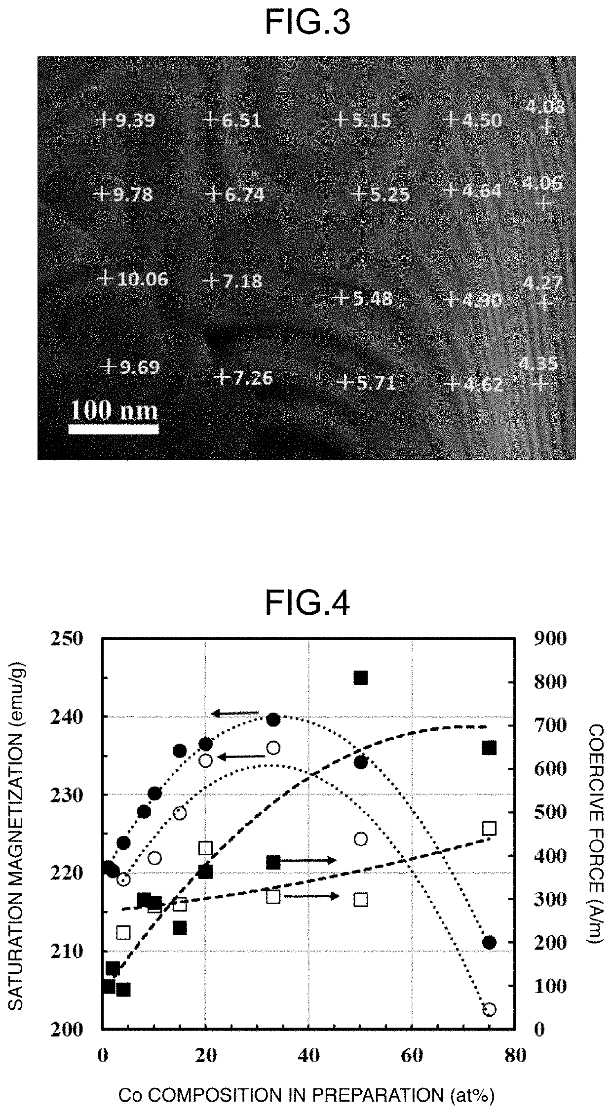
[0297]In FIG. 4, the measurement results of the saturation magnetization and the coercive force of Examples 1 to 17 are summarized with respect to the cobalt composition in preparation. In FIG. 4, ● and ▪ respectively represent values of the saturation magnetization (emu / g) and the coercive force (A / m) of the magnetic material ...

example 18

[0302]A magnetic powder of the present invention was obtained in the same manner as in Example 5 except that the reduction temperature was set to 550° C. It was found that the magnetic material of Example 18 was a semi-hard magnetic material of the present invention since a coercive force was 1670 A / m, which is a value more than 800 A / m and 40 kA / m or less. In addition, the saturation magnetization was 208.1 emu / g, which is an extremely high value among existing semi-hard magnetic materials, and the material had a good squareness ratio.

[0303]The measurement results of the phases, the crystallite size, and the magnetic properties of the magnetic powder of Example 18 are shown in Table 1. It was found that the Co-ferrite phase was slightly contained as the second phase by the XRD analysis.

[0304]It was confirmed that the crystallite size of the magnetic material of Example 18 reduced at 550° C. was about twice and the coercive force was 5.7 times as compared to the magnetic material of...


PUM

PropertyMeasurementUnit
volume fractionaaaaaaaaaa
average crystal grain sizeaaaaaaaaaa

Abstract

Provided are: a novel magnetic material having high magnetic stability, in particular, having an extremely high saturation magnetization; and a method for producing the same, wherein the magnetic material, due to having a higher saturation magnetization than ferrite magnetic materials and a higher electrical resistivity than existing metallic magnetic materials, resolves problems such as eddy current loss. According to the present invention, Co-ferrite nanoparticles obtained by wet synthesis are reduced in hydrogen and subjected to grain growth, and bcc- or fcc-(Fe, Co) phases and Co-enriched phases are nano-dispersed using phase separation via a disproportionation reaction to prepare a magnetic material powder. In addition, the magnetic material powder is sintered into a solid magnetic material.

Description

TECHNICAL FIELD[0001]The present invention relates to a magnetic material exhibiting soft magnetism or semi-hard magnetism, and in particular, a magnetic material exhibiting soft magnetism and a method for producing the same.BACKGROUND ART[0002]Global environmental problems, such as global warming and exhaustion of resources, are becoming more severe, and the social demands for energy saving and using less resources in various electronic and electric devices are increasing day by day. In such a situation, there is a need for further improvement in the performance of soft magnetic materials used in the drive unit of motors and the like and the transformer of voltage-conversion devices. In addition, to solve various problems involved with manufacturing various compact and high-performance information communication devices, increasing calculation processing speeds, increasing recording storage capacity, as well as maintaining environmental sanitation in infrastructure, distribution sys...

Claims


Application Information

Patent Timeline
Patent Type & Authority Applications(United States)
IPC IPC(8): H01F1/33H01F1/06H01F1/147H01F1/153B22F1/00
CPCH01F1/14775H01F1/15316H01F1/065H01F1/33H01F1/14741B22F1/00B22F3/00B22F9/22C22C19/07C22C38/00C22C2202/02C22C33/02B22F2998/10B22F2999/00C22C1/0433H01F1/147C22C38/10C22C38/02C22C38/04B22F3/02B22F3/10B22F2201/013
Inventor YAMAMOTO, SHINPEIIMAOKA, NOBUYOSHIOZAKI, KIMIHIRO
Owner NAT INST OF ADVANCED IND SCI & TECH
Why Eureka
Try Eureka