Thin film magnet, cylindrical ferromagnetic thin film and production method thereof

Inactive Publication Date: 2000-01-18
MITSUBISHI ELECTRIC CORP
View PDF2 Cites 16 Cited by
  • Summary
  • Abstract
  • Description
  • Claims
  • Application Information

AI Technical Summary

Benefits of technology

In addition, according to the present invention, there is provided a method for producing a ferromagnetic thin film in a cylindrical form having radial anisotropic magnetic properties by means of physical vapor deposition, the method including the steps of; heating a substrate in a cylindrical or columnar form to a predetermined temperature', and depositing a p

Problems solved by technology

Although sintered magnets have a large maximum energy product ranging up to 370 kJ/m.sup.3, they are very brittle and thus difficult to machine into a small size.
Therefore, sintered magnets are unsuitable for use as small-sized magnets.
However, this type of magnet has the disadvantage that the maximum energy product is as low as 40 to 120 kJ/m.sup.3 for mass-produced magnets and 170 kJ/m.sup.3 for Labaratory-produced magnets.
However, the above-described methods are unsuitable for produc

Method used


Image

  • Thin film magnet, cylindrical ferromagnetic thin film and production method thereof
  • Thin film magnet, cylindrical ferromagnetic thin film and production method thereof
  • Thin film magnet, cylindrical ferromagnetic thin film and production method thereof

Examples


example 1

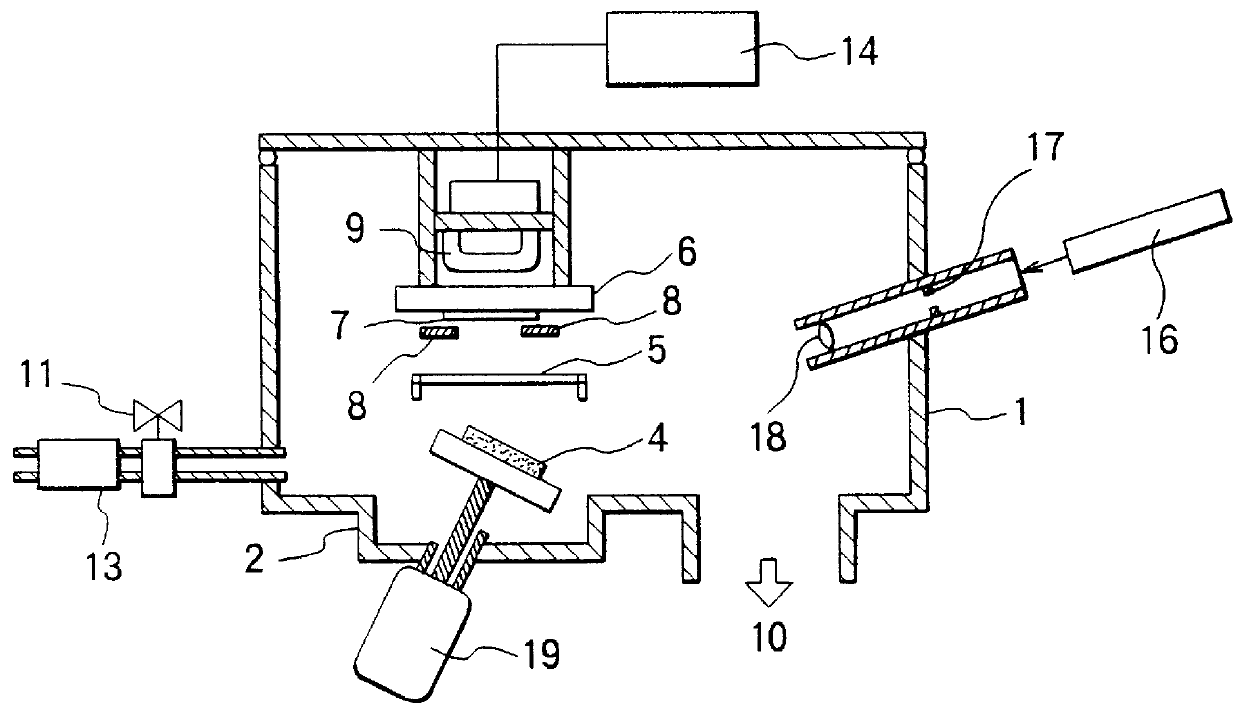
In the film deposition apparatus shown in FIG. 4, Nd--R (R is Tb, Ho, or Dy) serving as the target 4a, Fe metal as the target 4b, and an FeB alloy as the target 4c were attached to the cathode electrodes 3a, 3b, and 3c, respectively. The target 4a was made in such a manner that R metal chips having dimensions of 5 mm.times.5 mm.times.1 mm (thickness) was disposed on a 3 inch diameter Nd metal target. A 12 mm.times.12 mm.times.0.5 mm (thickness) quartz glass substrate was attached to the rotating substrate holder 20. The inside of the vacuum chamber 1 was then evacuated to a pressure less than 1.times.10.sup.-4 Pa via the pumping system 10. The substrate 7 was then heated by the heater 9 up to 590.degree. C.

After the temperature of the substrate 7 became stable, Ar gas was introduced into the vacuum chamber 1, and the gas pressure was maintained at 8 Pa. Substrate holder 20 was rotated by the motor 21. While maintaining the shutters 5a, 5b, and 5c in a closed state, voltages were app...

example 2

The film deposition apparatus shown in FIG. 4 was used, and Nd--Tb, M .[.fie--Co,.]. .Iadd.(Fe--Co, .Iaddend.Fe--Ni, or Fe--Co--Ni alloy), and an FeB alloy were employed as the targets 4a, 4b, and 4c, repectively. (Nd.sub.0.93 Tb.sub.0.07).sub.y M.sub.1-y-z B.sub.z thin film magnets having a thickness of about 2 .mu.m were formed on quartz glass substrates according to a procedure similar to that in Example 1 wherein the substrate temperature, the Ar gas pressure, and the deposition rate were 590.degree. C. 8 Pa, and 8 .mu.m / hr, respectively.

Table 6 shows the resultant magnetic characteristics measured perpendicular to the film plane for obtained thin film magnets. As can be seen from Table 6, the films show magnetic characteristics which are basically similar to those of the (Nd.sub.0.93 Tb.sub.0.07).sub.y Fe.sub.1-y-z B.sub.z thin film magnets described above with slight differences in the magnetic characteristics being observed depending on the changes in the Co and Ni compositio...

example 3

The film deposition apparatus shown in FIG. 4 was used. Nd-Tb, Fe metal, and an FeB alloy were employed as the targets 4a, 4b, and 4c, respectively, and (Nd.sub.1-x Tb.sub.x).sub.y Fe.sub.1-y-z B.sub.z thin film magnets having a thickness of about 2 .mu.m were formed on quartz glass substrates in a manner similar to that in Example 1, wherein the substrate temperature, the Ar gas pressure, and the deposition rate were 510.degree. to 590.degree. C. 8 Pa, and 8 .mu.m / hr, respectively.

FIG. 7 shows the magnetic characteristics of the thin film magnets obtained as a function of the substrate temperature upon. From FIG. 7, it can be seen that if a substrate temperature in the range from 530.degree. to 570.degree. C. is employed, it is possible to obtain particularly high coercive force and thus a large maximum energy product greater than at lease 140 kJ / m.sup.3.


PUM

PropertyMeasurementUnit
Pressureaaaaaaaaaa
Angleaaaaaaaaaa
Temperatureaaaaaaaaaa

Abstract

A thin film magnet and a cylindrical ferromagnetic thin film having a high maximum energy product (greater than 120 kJ/m3) and thus suitable for use in miniature high performance devices are provided. The thin film magnet is produced by means of physical vapor deposition. The thin film magnet is an (Nd1-xRx)yM1-y-zBz alloy having a ferromagnetic compound of the Nd2Fe14B type as its main phase, wherein R is Tb, Ho, and Dy and M is Fe metal or an Fe-based alloy including at least one of Co and Ni, 0.04</=x</=0.10,0.11</=y</=0.15, and 0.08</=z</=0.15. A perpendicular magnetization film having such a composition is deposited on the side wall of a substrate in the columnar (or cylindrical) form thereby obtaining a cylindrical ferromagnetic thin film having radial anisotropy.

Description

The present invention relates to a thin film magnet a ferromagnetic thin film in the form of a cylinder, and a production method thereof. More particularly, the present invention relates to a thin film magnet and a ferromagnetic thin film in the form of a cylinder for use in small-sized or miniature devices such as miniature electric motors, microwave oscillators, and micro-machines or magnetic recording devices. The invention also relates to a production method thereof.BACKGROUND OF THE INVENTIONIn recent years, significant advancements in performance as well as in size and weight reductions have been made in various devices such as video movie cameras, cassette tape recorders, communication equipment etc. These devices need a small-sized magnet, which is usually produced by machining a block of bonded or sintered magnet material.To improve the performance of such devices, it is desirable to employ a magnet having a high maximum energy product. On the other hand, in small-sized mag...

Claims


Application Information

Patent Timeline
IPC IPC(8): C23C14/28C23C14/06C23C14/34H01F41/02H01F41/20H01F1/057H01F1/032H01F10/12H01F41/14H01F10/14B81B1/00B81C1/00H01F41/18
CPCC23C14/06C23C14/067C23C14/28C23C14/3464H01F10/126H01F41/0273H01F41/20H01F1/057Y10T428/115
Inventor ARAKI, TAKESHITANI, YOSHIHIROIKEDA, HIDEOOKABE, MASASHI
Owner MITSUBISHI ELECTRIC CORP
Why Eureka
Try Eureka