Magnetic Material and Manufacturing Method Therefor

a magnetic material and manufacturing method technology, applied in the field of soft magnetic materials, can solve the problems of deterioration of magnetic properties, increased cost of punching and lamination steps, and increased cost of punching and lamination steps, and achieves high saturation magnetization, small eddy current loss, and high oxidation resistance.

Active Publication Date: 2019-04-11
NAT INST OF ADVANCED IND SCI & TECH
View PDF0 Cites 4 Cited by
  • Summary
  • Abstract
  • Description
  • Claims
  • Application Information

AI Technical Summary

Benefits of technology

[0025]According to the present invention, there can be provided a magnetic material having a high saturation magnetization and a small eddy current loss, in particular a soft magnetic material that is suitably used even in high rotation motors and the like, and various soft magnetic materials and semi-hard magnetic materials having high oxidation resistance.
[0026]According to the present invention, because the magnetic material can be used in the form of a powder material like ferrite, it can easily be produced in bulk by sintering or the like, and hence the present invention can solve problems such as complicated steps like lamination and the like caused by the use of metallic soft magnetic materials known as thin sheets, as well as the high costs involved with such steps.

Problems solved by technology

Global environmental problems, such as global warming and exhaustion of resources, are becoming more severe, and the social demands for energy saving and using less resources in various electronic and electric devices are increasing day by day.
Therefore, the costs of the punching and lamination steps, and deterioration of the magnetic properties are serious problems.
However, since this material is produced after first producing a ribbon by liquid rapid quenching, the thickness of the product is about 0.02 to 0.025 mm, and the insulation, cutting, alignment, lamination, welding, and annealing steps are more complicated than for silicon steel, this material suffers from problems such as processability and thermal stability.
Furthermore, the electric resistivity is small at 1.2 μΩm, and a problem with eddy current loss similar to other rolled materials and ribbons has been pointed out.
However, the magnetic properties are much worse than for a 20 μm ribbon, with a coercive force of 300 A / m and a saturation magnetization of 1 T. At present, there is no good method other than a lamination method for producing products thicker than 0.5 mm.
However, the coercive force of this material is comparatively high, namely, 2 to 160 A / m, and in particular, the saturation magnetization is small at 0.3 to 0.5 T. Therefore, this material is not suitable for high-performance, high-speed motors for next-generation automobiles, for example.
However, such materials have a low electric resistance, and suffer from the occurrence of eddy current loss for high-rotation, high-performance motors.
This results in serious problems such as the steps becoming complicated, an insulation treatment before lamination being necessary, magnetic properties deteriorating due to punching and the like, and increased costs for the steps.
On the other hand, oxide-based soft magnetic materials such as ferrite have a large electric resistance and no problems with eddy current loss, but they are unsuitable for high-performance motors for next-generation automobiles because they have a small saturation magnetization of 0.5 T or less.
The steps of insulating, punching, aligning, welding and annealing such a thin sheet are complicated and expensive.

Method used


Image

  • Magnetic Material and Manufacturing Method Therefor
  • Magnetic Material and Manufacturing Method Therefor
  • Magnetic Material and Manufacturing Method Therefor

Examples


examples 14 to 16

[0288]Magnetic materials of the present invention were produced in the same manner as in Example 13, except that the Mn content was set to the amount shown in Table 3. In all the examples, the presence of the first phase and the presence of the second phase were confirmed.

[0289]The measurement results of the phases, compositions, particle diameters, and magnetic properties of these examples are shown in Table 3.

[0290]It is also noted that the analysis of the Mn composition amount and the like of the bcc phase was carried out in the same manner as in Example 13.

[0291]In these examples, the K content relative to the whole magnetic material including Mn, Fe, O, and K was 0 atom %.

examples 17 and 18

[0292]Magnetic materials of the present invention were produced in the same manner as in Example 9, except that the Mn content, the reduction temperature, and the reduction time were set as shown in Table 4, and the rate of temperature increase and rate of temperature decrease were set as shown in Table 4. Further, in both the examples, the presence of the first phase and the presence of the second phase were confirmed. The measurement results of the phases, compositions, particle diameters, and magnetic properties of these examples are shown in Table 4. For comparison, the results of Example 9 in Table 1 are also provided in Table 4.

[0293]The “fast” condition and the “slow” condition of the rate of temperature increase / decrease shown in Table 4 are as follows.

(Rate of Temperature Increase)

[0294]“Fast”: Temperature is increased at 10° C. / min until the predetermined reduction temperature.

“Slow”: Temperature is increased at 10° C. / min up to 300° C., and from 300° C. to the predetermin...

example 19

[0297]The magnetic material powder of Example 9 was placed in a 3 ϕ cemented carbide metal die made of tungsten carbide, and then electric current sintering was carried out in a vacuum at 150° C. under 1.4 GPa.

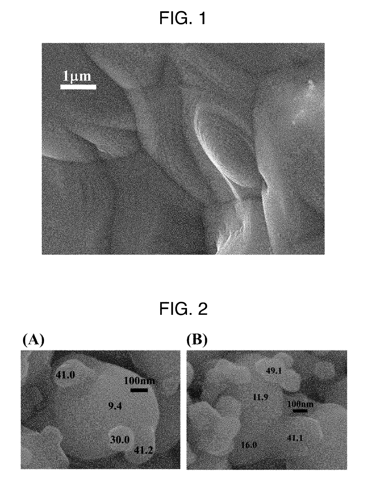
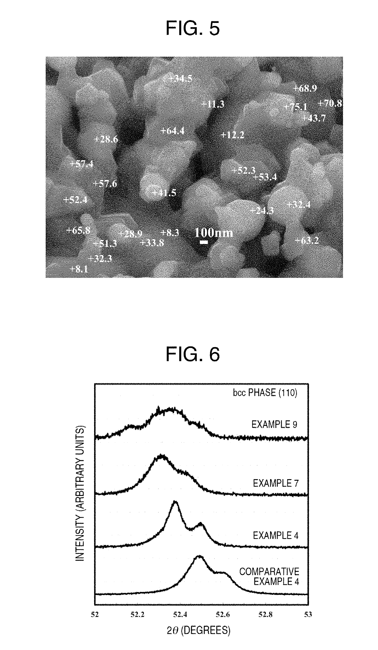
[0298]Next, this electrically-sintered body was annealed in hydrogen at 1000° C. for 1 hour to prepare a solid magnetic material. The “slow” condition was selected as the rate of temperature increase and the “fast” condition was selected as the rate of temperature decrease. FIG. 9 is an SEM image of the surface of the solid magnetic material of this example. A large number of crystal boundaries were observed to be present in the sintered layer. FIG. 10 is an oxygen characteristic X-ray surface distribution map of the region of FIG. 9 obtained using SEM-EDX. In the white part, the oxygen content is high, and it can be seen that this part is a wustite phase. In the other examples as well, a method that is basically the same as this was employed when distinguishing whether the ph...


PUM

PropertyMeasurementUnit
volume fractionaaaaaaaaaa
crystal grain sizeaaaaaaaaaa

Abstract

Provided is a new magnetic material with high magnetic stability, as well as a manufacturing method therefor, said magnetic material having a higher saturation magnetization than ferrite-based magnetic materials, and having a higher electrical resistivity than existing metal-based magnetic materials, thus solving problems such as that of eddy current loss. Mn-ferrite nanoparticles obtained through wet synthesis are reduced within hydrogen, and grains are allowed to grow while simultaneously using a phase separation phenomenon due to a disproportionation reaction to produce a magnetic material powder in which an α-(Fe, Mn) phase and a Mn-enriched phase are nano-dispersed. This powder is then sintered to produce a solid magnetic material.

Description

TECHNICAL FIELD[0001]The present invention relates to a soft magnetic material or a semi-hard magnetic material, and a production method thereof.BACKGROUND ART[0002]Global environmental problems, such as global warming and exhaustion of resources, are becoming more severe, and the social demands for energy saving and using less resources in various electronic and electric devices are increasing day by day. In such a situation, there is a need for further improvement in the performance of soft magnetic materials used in the drive unit of motors and the like and the transformer of voltage-conversion devices. In addition, to solve various problems involved with manufacturing various compact and high-performance information communication devices, increasing calculation processing speeds, increasing recording storage capacity, as well as maintaining environmental sanitation in infrastructure, distribution systems that are becoming ever more complex, and strengthening the security that be...

Claims


Application Information

Patent Timeline
Patent Type & Authority Applications(United States)
IPC IPC(8): B22F1/00B22F3/24C22C22/00C22C33/02C22C38/04H01F1/147H01F1/22H01F1/33H01F1/34B22F1/08
CPCB22F1/0003B22F3/24C22C22/00C22C33/02C22C38/04H01F1/147H01F1/22H01F1/33H01F1/34C22C38/00H01F1/0306B82Y25/00B22F1/08H01F1/20
Inventor IMAOKA, NOBUYOSHIOZAKI, KIMIHIRO
Owner NAT INST OF ADVANCED IND SCI & TECH
Why Eureka
Try Eureka