Magnetic Material and Manufacturing Method Therefor

a magnetic material and manufacturing method technology, applied in the field of soft magnetic materials, can solve the problems of deterioration of magnetic properties, increased cost of punching and lamination steps, and increased cost of punching and lamination steps, and achieves high saturation magnetization, small eddy current loss, and high oxidation resistance.

Active Publication Date: 2019-02-14
NAT INST OF ADVANCED IND SCI & TECH
View PDF0 Cites 5 Cited by
  • Summary
  • Abstract
  • Description
  • Claims
  • Application Information

AI Technical Summary

Benefits of technology

[0025]According to the present invention, there can be provided a magnetic material having a high saturation magnetization and a small eddy current loss, in particular a soft magnetic material that is suitably used even in high rotation motors and the like, and various soft magnetic materials and semi-hard magnetic materials having high oxidation resistance.
[0026]According to the present i

Problems solved by technology

Global environmental problems, such as global warming and exhaustion of resources, are becoming more severe, and the social demands for energy saving and using less resources in various electronic and electric devices are increasing day by day.
Therefore, the costs of the punching and lamination steps, and deterioration of the magnetic properties are serious problems.
However, since this material is produced after first producing a ribbon by liquid rapid quenching, the thickness of the product is about 0.02 to 0.025 mm, and the insulation, cutting, alignment, lamination, welding, and annealing steps are more complicated than for silicon steel, this material suffers from problems such as processability and thermal stability.
Furthermore, the electric resistivity is small at 1.2 μΩm, and a problem with eddy current loss similar to other rolled materials and ribbons has been pointed out.
However, the magnetic properties are much worse than for a 0.02 mm ribbon, with a coercive force of 300 A/m and a saturation magnetization of 1 T. At present, there is no good method other than a lamination method for prod

Method used


Image

  • Magnetic Material and Manufacturing Method Therefor
  • Magnetic Material and Manufacturing Method Therefor
  • Magnetic Material and Manufacturing Method Therefor

Examples


example 2

[0259]The Ti-ferrite nanopowder of Comparative Example 1 having a (Fe0.951Ti0.049)43O57 composition and an average powder particle diameter of 20 nm was placed in a crucible made of aluminum titanate, the temperature was increased at 10° C. / min up to 300° C. in a hydrogen flow, then increased from 300° C. to 600° C. at 2° C. / min, and a reduction treatment was carried out at 600° C. for 1 hour. After that, the temperature was lowered at a rate of 45° C. / min to 400° C., and then cooled from 400° C. to room temperature over 40 minutes. Next, a gradual oxidation treatment was carried out at 20° C. in an argon atmosphere having an oxygen partial pressure of 1% by volume for 1 hour to obtain a magnetic material having a composition ratio of titanium to iron of Fe94.4Ti5.6. At this time, based on the whole magnetic material including Ti, Fe, O, and K, the O content was 6.0 atom % and the K content was 0.2 atom %. Further, the average powder particle diameter of the Fe—Ti magnetic material ...

examples 3 to 11

[0273]Magnetic materials of the present invention were produced in the same manner as in Example 1, except that the reduction temperature was set to that shown in Table 1 within the range of 450° C. to 1200° C., and a rate v of temperature decrease (° C. / min) until 400° C. was set to, when the reduction temperature is taken to be T (° C.), a velocity represented by the following relational expression.

[Expression 2]

v=0.1T−15  (2)

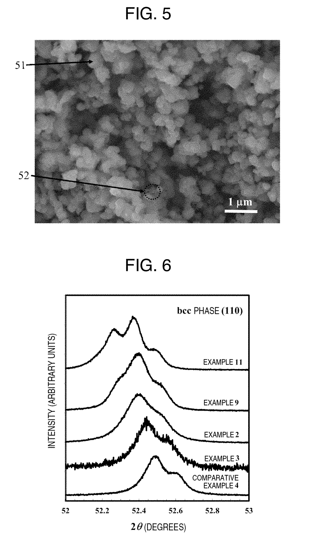
[0274]The measurements were also carried out in the same manner as in Example 1. In all of the examples, it was confirmed that an α-(Fe,Ti) phase (first phase) and a phase (second phase) having a larger Ti content than that phase were formed in the observed magnetic material. It was also confirmed that, in Example 3, a first phase of α-(Fe,Ti) phase and a second phase (specifically, a titanomagnetite phase and a wustite phase) having a Ti content of less than 2 atom % but two times or more and 105 times or less than that of the first phase were formed in the ...

example 12

[0281]An Fe—Ti metal powder was prepared in the same manner as in Example 5, except that the reduction conditions were changed to 550° C. for 4 hours. The measurements were also carried out in the same manner as in Example 1. With a reduction time of 4 hours, the reduction reaction advanced and the titanohematite phase and the titanomagnetite phase, which did not disappear on XRD for a reduction time of 1 hour at 550° C., disappeared. From the results of the SEM observation, it was also found that the magnetic material of this example was a mixed phase of an α-(Fe,Ti) phase and a spawn phase. Further, in this example, it was also confirmed that the observed magnetic material contained an α-(Fe,Ti) phase (first phase) and a phase (second phase) having a larger Ti content than that phase.

[0282]The measurement results of the phases, composition, particle diameter, and magnetic properties of this example are summarized in Table 1.


PUM

PropertyMeasurementUnit
Grain sizeaaaaaaaaaa
Temperatureaaaaaaaaaa

Abstract

Provided is a new magnetic material with high magnetic stability, as well as a manufacturing method therefor, said magnetic material having a higher saturation magnetization than ferrite-based magnetic materials, and having a higher electrical resistivity than existing metal-based magnetic materials, thus solving problems such as that of eddy current loss. Ti-ferrite nanoparticles obtained through wet synthesis are reduced within hydrogen, and grains are allowed to grow while simultaneously using a phase separation phenomenon due to a disproportionation reaction to produce a magnetic material powder in which an α-(Fe, Ti) phase and a Ti-enriched phase are nano-dispersed. This powder is then sintered to produce a solid magnetic material.

Description

TECHNICAL FIELD[0001]The present invention relates to a soft magnetic material or a semi-hard magnetic material, and a production method thereof.BACKGROUND ART[0002]Global environmental problems, such as global warming and exhaustion of resources, are becoming more severe, and the social demands for energy saving and using less resources in various electronic and electric devices are increasing day by day. In such a situation, there is a need for further improvement in the performance of soft magnetic materials used in the drive unit of motors and the like and the transformer of voltage-conversion devices. In addition, to solve various problems involved with manufacturing various compact and high-performance information communication devices, increasing calculation processing speeds, increasing recording storage capacity, as well as maintaining environmental sanitation in infrastructure, distribution systems that are becoming ever more complex, and strengthening the security that be...

Claims


Application Information

Patent Timeline
IPC IPC(8): H01F1/147H01F41/02B22F1/08B22F1/16
CPCH01F1/14791H01F1/14733H01F41/0246B22F1/02B22F3/003B22F9/22C22C14/00C22C38/00H01F1/33H01F1/346H01F1/26H01F1/36C22C32/001B22F2998/10C22C2202/02B22F3/00H01F1/0306B82Y25/00H01F1/147B22F1/16B22F1/08H01F1/22H01F1/34H01F1/20
Inventor IMAOKA, NOBUYOSHIOZAKI, KIMIHIRO
Owner NAT INST OF ADVANCED IND SCI & TECH
Why Eureka
Try Eureka