Hybrid grow light

a hybrid grow light and grow light technology, applied in lighting applications, lighting and heating equipment, with built-in power, etc., can solve the problem of poor return on investment (roi) given the high initial cost of the system

Inactive Publication Date: 2012-11-15
MODERN WOODWORKS
View PDF2 Cites 23 Cited by
  • Summary
  • Abstract
  • Description
  • Claims
  • Application Information

AI Technical Summary

Benefits of technology

[0009]What is desired is to provide a horticulture grow light that overcomes the disadvantages of current systems as noted hereinabove.

Problems solved by technology

Even though systems #2 and #3 deliver a 20-30% savings in power over system #1, the return on investment (ROI) is poor given the high initial cost of the system.

Method used


Image

  • Hybrid grow light
  • Hybrid grow light
  • Hybrid grow light

Examples


Embodiment Construction

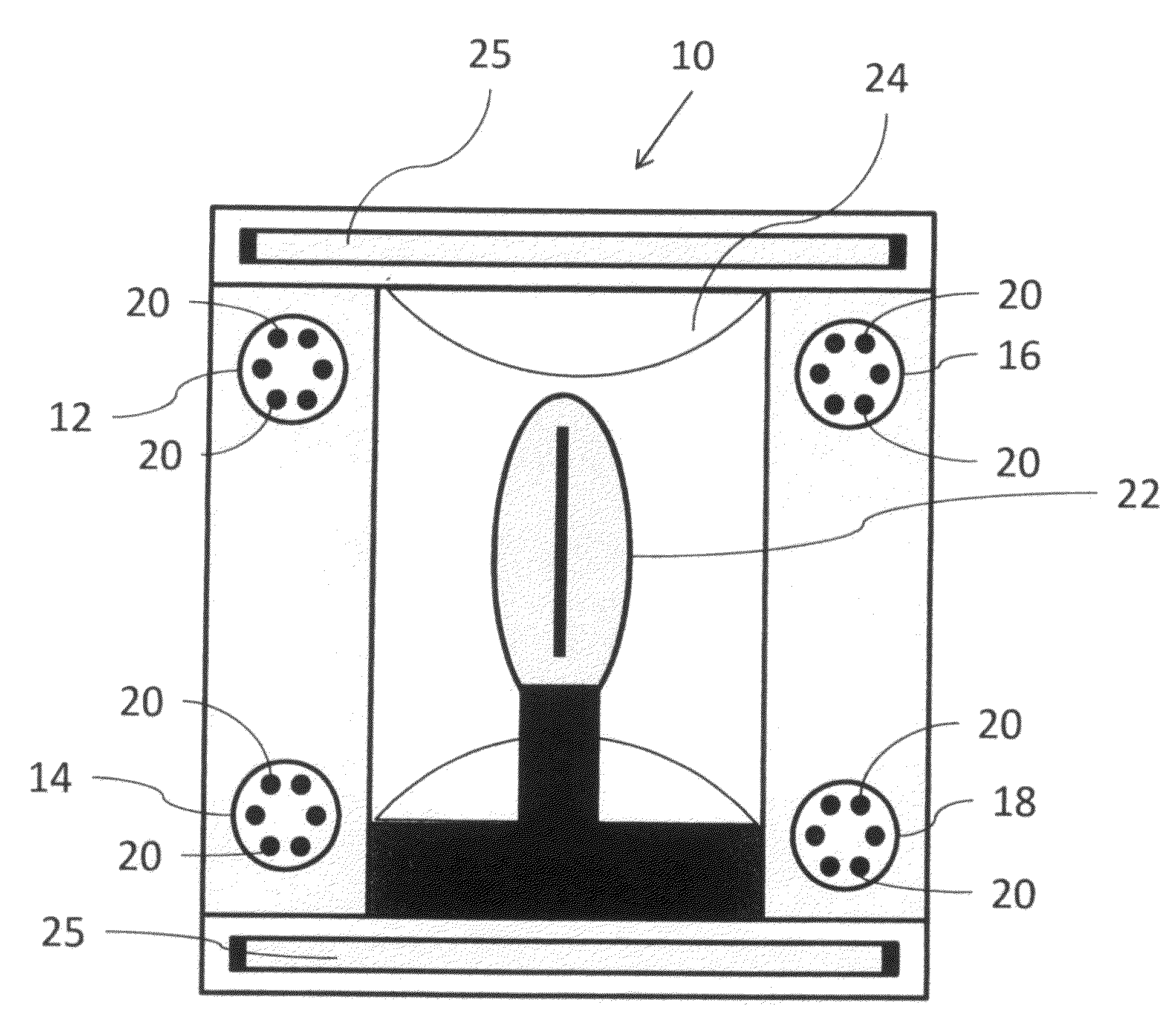
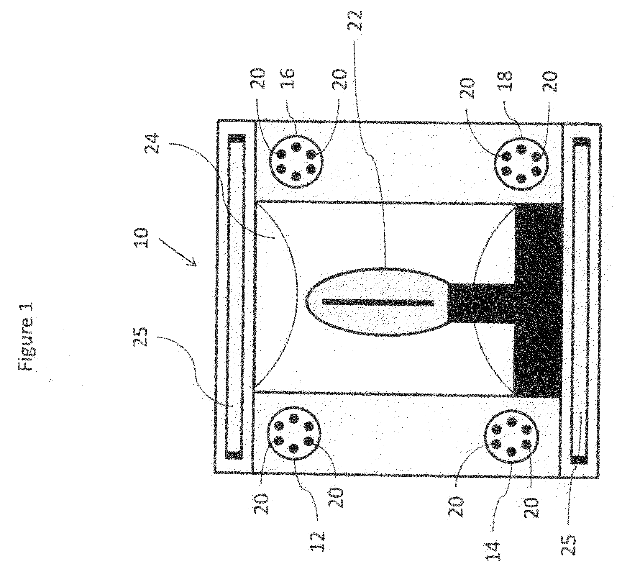
[0029]FIG. 1 is a bottom view of the light system 10 of the present invention and shows four LED light sources 12, 14, 16 and 18 that each consist of a plurality of LED emitters 20 (six shown in the figure) in various color combinations to optimize plant photosynthesis. The LED light sources are LEDs mounted on a printed circuit board (either metal core PCB or standard FR4 PCB) and mated to a heat sink since good thermal management is essential to the performance and lifetime of the LED emitters. Recently developed LED light sources can be made with larger footprints and encapsulate twelve or more LED emitters of different peak wavelengths (colors) in a single package.

[0030]In addition to the four LED light sources noted hereinabove, light system 10 includes an HID light source 22 at the center light system 10 as shown in FIG. 1. The HID light source can either be MH or BPS based systems designed with a ballast that can accommodate either type of light source (the HID light source r...


PUM


Abstract

A light system for growing plants indoors comprising three light sources each having a different range of wavelengths, power being applied to each light source at an intensity, combination and sequence determined by the growing properties of the plants.

Description

BACKGROUND OF THE INVENTION[0001]1. Field of the Invention[0002]The present invention provides a light source assembly utilized in the field of indoor horticulture lighting, the light source assembly comprising at least three separate light sources each emitting light of a different frequency.[0003]2. Description of the Prior Art[0004]High intensity discharge (“HID”) lights have been used in indoor horticulture for many years. Specifically, there are two types of HID lights used for indoor growing: metal halide (MH) and high pressure sodium (HPS) based systems. MH lights have a blue tinge and are typically used during vegetative growth. HPS lights emit a yellowish / red tint and are used for the flowering portion of the grow process.[0005]The field of light emitting diodes (LED) is a rapidly advancing technology that has the promise to significantly reduce power consumption for general lighting as well as for indoor horticulture. Over the last five years, ever brighter and more effici...

Claims


Application Information

Patent Timeline
Patent Type & Authority Applications(United States)
IPC IPC(8): F21S10/02
CPCA01G7/045F21S10/023F21Y2101/02A01G9/249F21Y2101/00F21Y2115/10Y02P60/14
Inventor MEKHTARIAN, GEORGE
Owner MODERN WOODWORKS
Why Eureka
Try Eureka