
Hybrid fiber-rod laser

a fiber-rod laser and hybrid technology, applied in the field of single-mode operation of optical waveguides, can solve the problems of increasing the precision with which refractive index control must be integrated, and going to larger core area fibers that are truly single-mode, and achieve the effect of expanding the parameter space accessible and increasing the transverse mode area

Active Publication Date: 2012-11-15
LAWRENCE LIVERMORE NAT SECURITY LLC
View PDF35 Cites 4 Cited by
  • Summary
  • Abstract
  • Description
  • Claims
  • Application Information

AI Technical Summary

Problems solved by technology

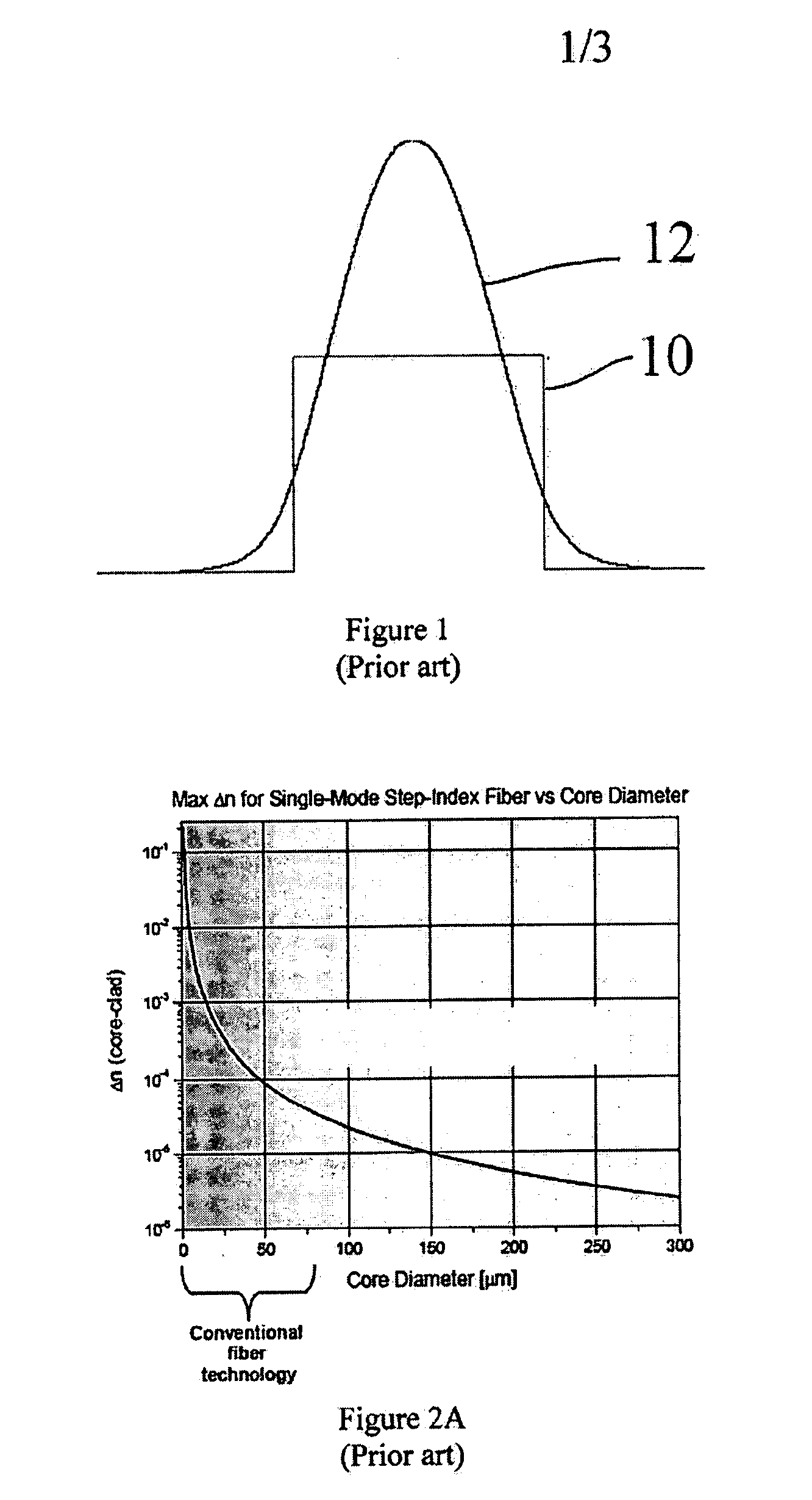
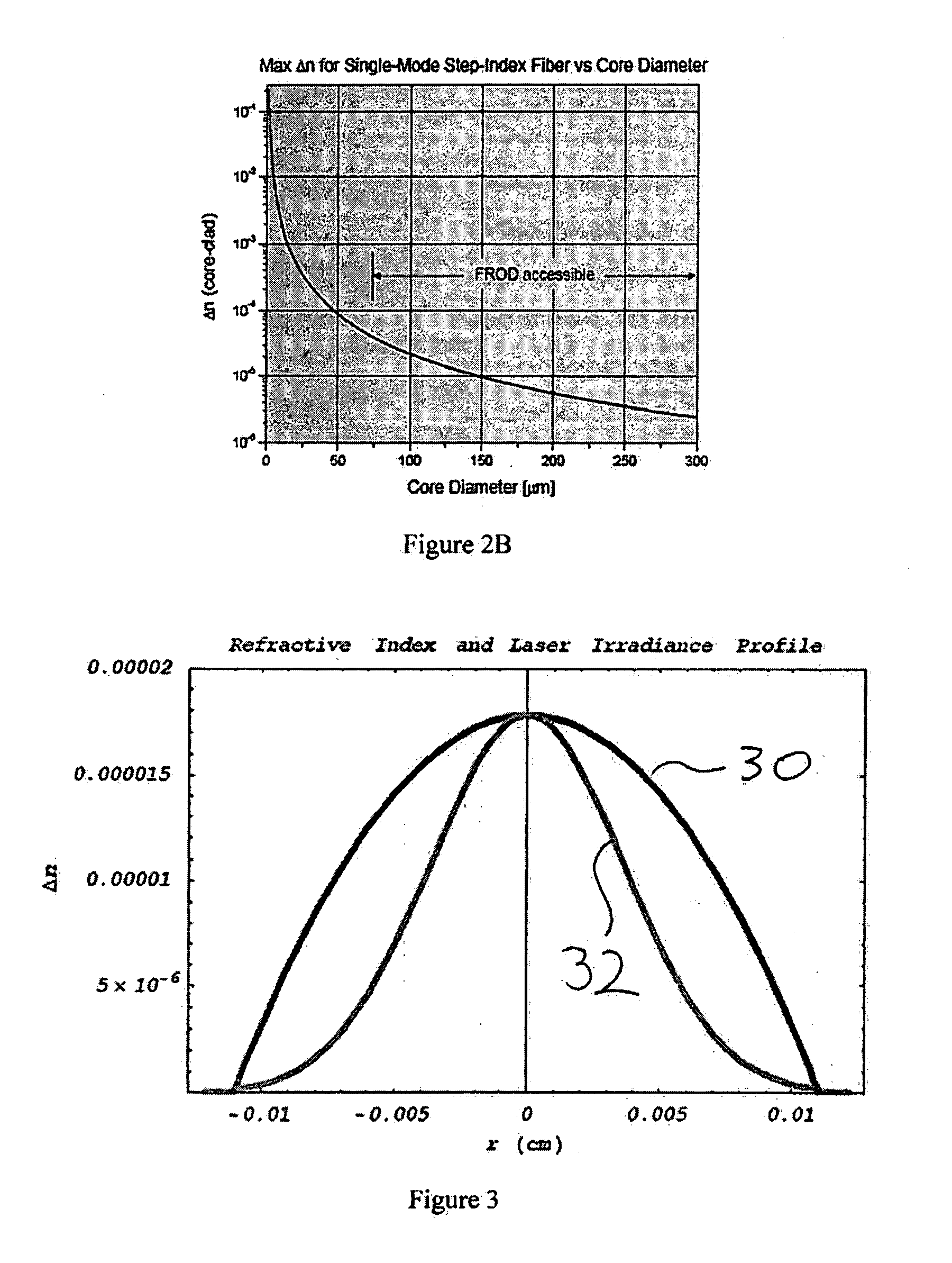
The practical limit in going to larger core area fibers that are truly single mode is the increased precision with which refractive index control must be incorporated into the waveguide.

Method used


Image

  • Hybrid fiber-rod laser
  • Hybrid fiber-rod laser
  • Hybrid fiber-rod laser

Examples


Embodiment Construction

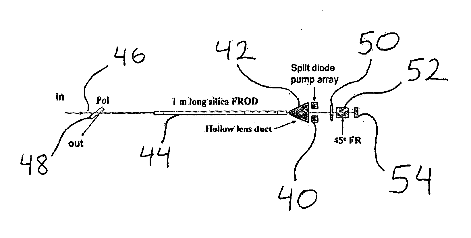
[0027]The present invention surpasses the limits imposed by conventional fiber technologies by using a thermally generated waveguide rather than one fabricated directly into the waveguide material itself. Because fused silica has a positive dn / dT, when a fiber is pumped and heat is uniformly generated throughout the fiber's doped core, a parabolic temperature profile is naturally established with the center of the core the hottest and the perimeter the coolest. This leads to a refractive index gradient across the fiber that follows the temperature gradient, with the fiber core's center having the highest refractive index. Using the refractive index profile established by the temperature gradient in the fiber, it is then possible to guide radiation in exact analogy to conventional fibers where the step index structure does the guiding. The advantage with the thermal guiding approach is that now the waveguide can be constructed from a single homogeneous material, which can have a very...


PUM


Abstract

Single, or near single transverse mode waveguide definition is produced using a single homogeneous medium to transport both the pump excitation light and generated laser light. By properly configuring the pump deposition and resulting thermal power generation in the waveguide device, a thermal focusing power is established that supports perturbation-stable guided wave propagation of an appropriately configured single or near single transverse mode laser beam and / or laser pulse.

Description

[0001]This application claims priority to U.S. Provisional Patent Application Ser. No. 60 / 810,094, titled: “Hybrid Fiber-ROD Laser (FROD)”, filed May 31, 2006, which application is incorporated herein by reference.[0002]The United States Government has rights in this invention pursuant to Contract No. W-7405-ENG-48 between the United States Department of Energy and the University of California for the operation of Lawrence Livermore National Laboratory.BACKGROUND OF THE INVENTION[0003]1. Field of the Invention[0004]The present invention relates to optical waveguides, and more specifically, it relates to single mode operation of optical waveguides.[0005]2. Description of Related Art[0006]Today the most common fiber structures consist of a single step index that serves to confine radiation as it is propagated along the length of a fiber. By appropriately coordinating the magnitude of the jump in the step index together with the diameter of the laser core, it is possible to ensure only...

Claims


Application Information

Patent Timeline
Patent Type & Authority Applications(United States)
IPC IPC(8): H01S3/067
CPCH01S3/06754H01S3/08072H01S3/08077H01S3/094057H01S3/176H01S3/1022H01S3/1312H01S3/1618H01S3/09415H01S3/1001
Inventor BEACH, RAYMOND J.DAWSON, JAY W.MESSERLY, MICHAEL J.BARTY, CHRISTOPHER P.J.
Owner LAWRENCE LIVERMORE NAT SECURITY LLC
Learn More