Scroll type fluid machine

a fluid machine and roll type technology, applied in the direction of machines/engines, liquid fuel engines, rotary piston liquid engines, etc., can solve the problems of increasing the weight of the components, increasing the amount of centrifugal force applied, increasing the cost, etc., to improve the durability of the interlocking mechanism, reduce the amount of space required, and reduce the centrifugal force exerted on the interlocking mechanism.

Inactive Publication Date: 2012-11-15
ANEST IWATA CORP
View PDF4 Cites 17 Cited by
  • Summary
  • Abstract
  • Description
  • Claims
  • Application Information

AI Technical Summary

Benefits of technology

[0019]Note that in the present invention, the rotary bearings interposed in the respective sliding surfaces between the recessed portion and the rotary body and between the eccentric hole and the pin member include sliding bearings and rolling bearings, for example. Further, the sliding bearing includes a case in which a bearing layer is formed by implementing quench hardening treatment, surface hardening treatment, or friction reduction treatment on a surface of the recessed portion, the rotary body, or the pin member forming the sliding surfaces such that these components can slide favorably on the sliding surfaces.
[0020]The apparatus according to the present invention preferably further includes a coupling body that is disposed in a position facing a back surface of one of the end plates of the driving scroll and the driven scroll and coupled to an outer peripheral site of the other end plate, wherein the interlocking mechanism is interposed between the other end plate and the coupling body. Thus, a disposal position of the interlocking mechanism is not restricted by the spiral laps, and therefore the interlocking mechanism can be disposed further toward a central side of the endplates than the spiral laps. As a result, the centrifugal force exerted on the interlocking mechanism can be reduced even further, enabling a further improvement in the durability of the interlocking mechanism.
[0021]Note that the coupling body is preferably constituted by a ring-shaped disc having in a central portion thereof a through hole through which a shaft portion of the scroll is passed, and a coupling portion that is coupled to the outer peripheral site of the one end plate is preferably formed on an outer peripheral end of the coupling body. Thus, the coupling body can be formed compactly, enabling a reduction in an amount of space required to dispose the coupling body. As a result, the scroll fluid machine can be reduced in size.
[0022]In the apparatus according to the present invention, the rotary bearings interposed respectively between the recessed portion and the rotary body and between the eccentric hole and the pin member are preferably either sliding bearings or rolling bearings such as ball bearings or roller bearings. Thus, sliding between the recessed portion and the rotary body and between the eccentric hole and the pin member can be performed smoothly. As a result, burns and wear on the respective sliding surfaces can be eliminated. When rolling bearings are used, sliding between the respective members can be performed particularly smoothly.
[0023]When the rotary bearings are formed from a self-lubricating material having a low frictional coefficient, such as fluorine resin, lubricating oil is not required. Further, when rolling bearings are used as the rotary bearings, grease can be sealed therein easily, thus eliminating the need for lubricating oil.
[0024]According to the present invention, in a scroll type fluid machine including: a driving scroll driven to rotate by a drive source; a driven scroll disposed in an offset position relative to an axial center of the driving scroll in order to compress or expand a fluid in conjunction with the driving scroll; and an interlocking mechanism that causes the driven scroll to rotate synchronously in conjunction with rotation of the driving scroll while performing a revolving motion about the axial center of the driving scroll, the interlocking mechanism includes: a columnar or conical rotary body that includes an eccentric hole formed in an axial direction and is loosely fitted into a columnar or conical recessed portion provided as a recess in one of respective end plates of the driving scroll and the driven scroll in a site where the respective end plates oppose each other; a pin member that projects from another of the end plates and is inserted loosely into the eccentric hole; and a rotary bearing interposed in respective sliding surfaces between the recessed portion and the rotary body and between the eccentric hole and the pin member, and the interlocking mechanism is provided in a plurality of locations in a circumferential direction of the scroll. Therefore, in addition to the advantages obtained with the pin crank system described above, an excessive moment load and an offset load are not exerted on the rotary body and the bearings. Hence, rotary force can be transmitted from the driving scroll to the driven scroll with stability, and wear on the respective sliding surfaces between the recessed portion and the rotary body and between the eccentric hole and the pin member can be reduced. As a result, the lifespan of the rotary body and the bearings can be increased. Further, since the rotary body and the bearings do not have to be manufactured using a high strength material, a reduction in cost can be achieved.

Problems solved by technology

Furthermore, it is necessary to increase a durability of the interlocking mechanism 122, and for this purpose, the columnar solid body 124, the columnar projecting portions 126, 128, and so on must be manufactured from high strength materials, leading to an increase in cost.
Moreover, when these components are manufactured from a high strength material such as a steel material, the weight of the components increases, and as a result, the applied centrifugal force increases further.

Method used


Image

  • Scroll type fluid machine
  • Scroll type fluid machine
  • Scroll type fluid machine

Examples


first embodiment

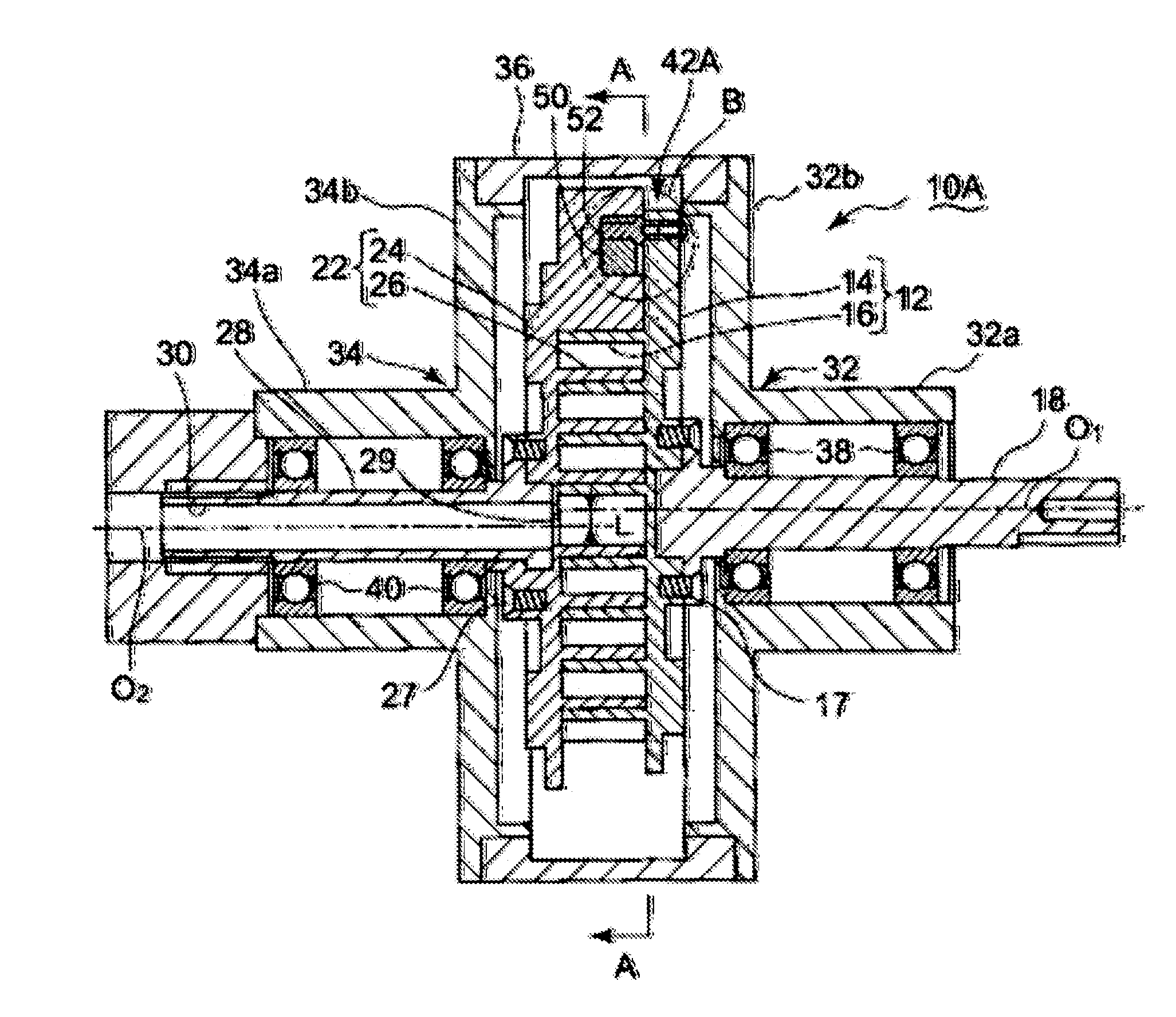
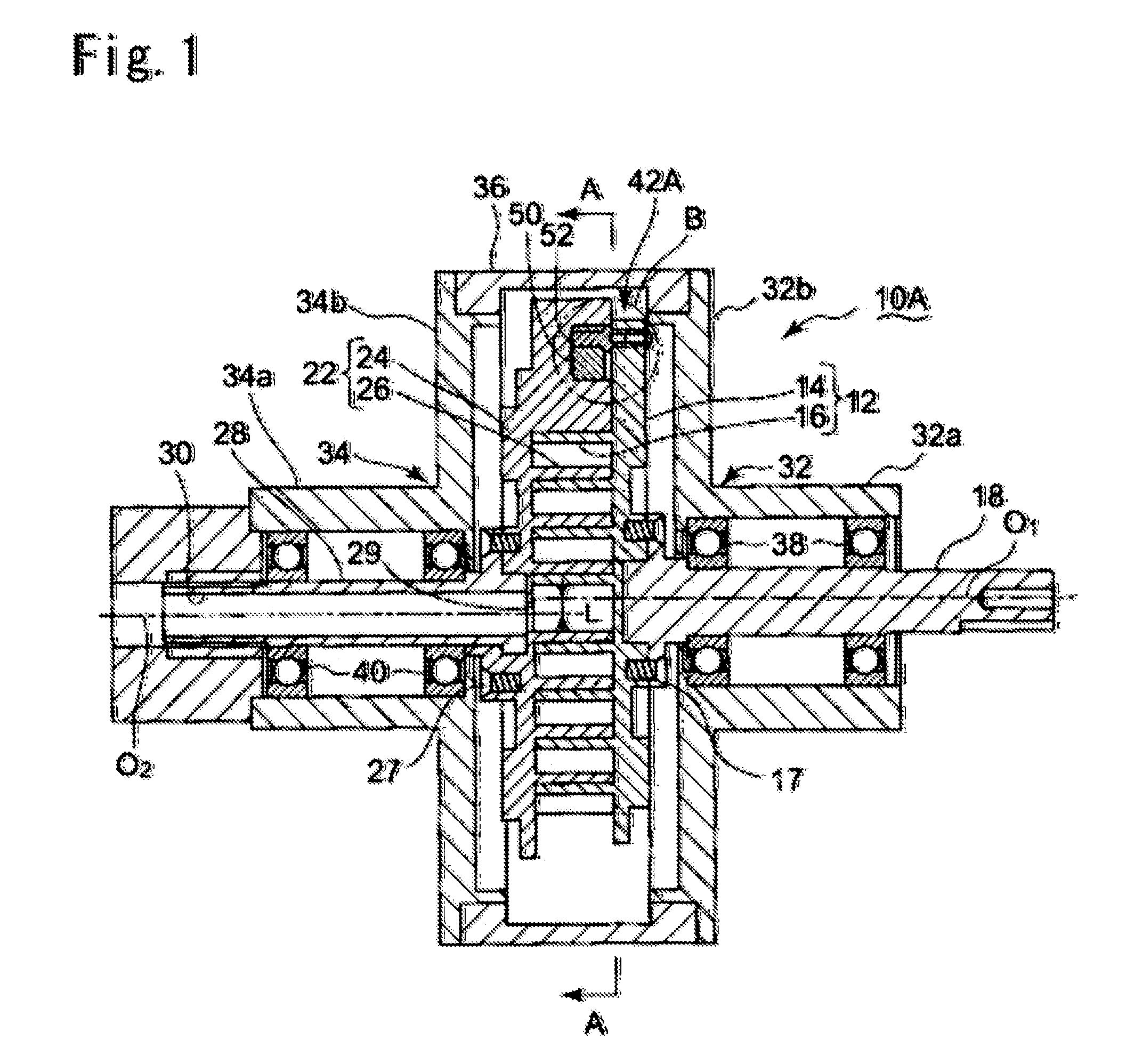
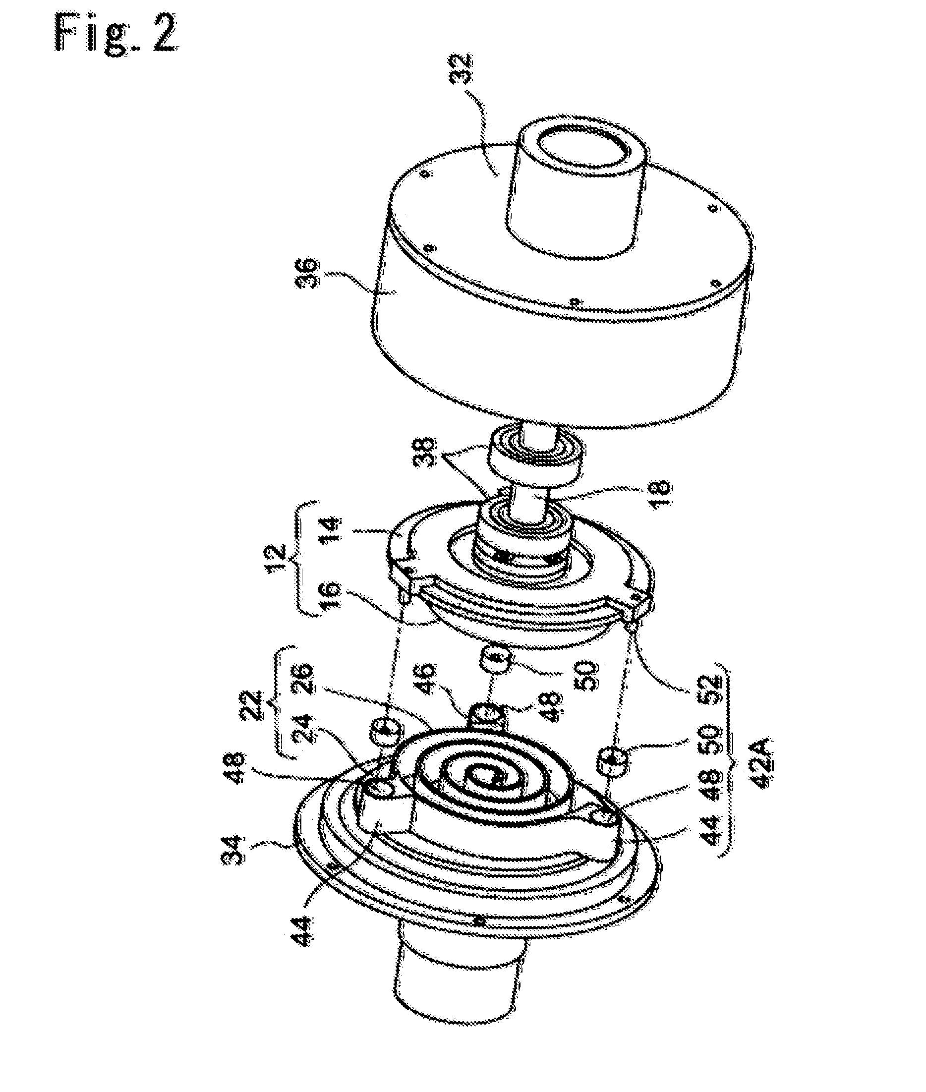
[0039]A first embodiment in which the present invention is applied to a scroll type compressor will be described below on the basis of FIGS. 1 to 6. In FIGS. 1 to 3, a scroll type compressor 10A according to this embodiment includes a driving scroll 12 and a driven scroll 22 disposed to be mutually interlocked. The driving scroll 12 is constituted by a disc-shaped end plate 14 and a spiral lap 16 formed integrally with the end plate 14, and is driven to rotate by a drive shaft 18 that is coupled to the end plate 14 by a bolt. The drive shaft 18 is coupled to a driving motor (not shown).

[0040]The driven scroll 22 is constituted by a disc-shaped end plate 24 and a spiral projection 26 formed integrally with the end plate 24, and a driven shaft 28 is coupled to the end plate 24 by a bolt 27. A discharge port 29 for discharging a compressed compressible fluid is provided in a center of the end plate 24. A rotary center O2 of the driven shaft 28 is positioned to be offset from a rotary c...

second embodiment

[0050]Next, a second embodiment in which the present invention is applied to a scroll compressor will be described using FIG. 7. In an interlocking mechanism 42B according to this embodiment, instead of forming the bearing layer 50a on the outer peripheral surface of the rotary body 50 and the inner peripheral surface of the eccentric hole 51, a rolling bearing (a roller bearing) 60 is interposed in the sliding surface between the recessed portion 48 and the rotary body 50, and a needle bearing 62 is interposed in the sliding surface between the eccentric hole 51 and the pin member 52. All other configurations are identical to the first embodiment.

[0051]By providing the interlocking mechanism 42B according to this embodiment with the rolling bearing 60 and the needle bearing 62, relative rotation between the recessed portion 48 and the rotary body 50 can be performed more smoothly. Further, grease can be sealed easily into the rolling bearing 60 and the needle bearing 62, and theref...

third embodiment

[0052]Next, a third embodiment of the apparatus according to the present invention will be described using FIGS. 8 to 10. In a scroll compressor 10B according to this embodiment, an outer diameter of the end plate 24 of the driven scroll 22 is formed to be larger than an outer diameter of the end plate 14 of the driving scroll 12. An opposing surface 70a of a coupling cap 70 is disposed to face the back surface 14c side of the end plate 14. A through hole 72 through which the drive shaft 18 passes is provided in a center of the coupling cap 70. Further, coupling portions 74 that project toward the end plate 24 side are formed integrally with the coupling cap 70 at equal intervals in three locations on an outer peripheral end thereof.

[0053]The coupling portions 74 are provided in positions opposing lower step surfaces 44b and 46b of the respective bases 44 and 46, and joined to the lower step surfaces 44b, 46b by bolts. In an interlocking mechanism 42C according to this embodiment, t...


PUM


Abstract

To realize an increase in lifespan and a reduction in cost in an interlocking mechanism that causes a driving scroll and a driven scroll to rotate synchronously, a through hole is drilled into a peripheral edge portion of a driving scroll side end plate, and a pin member is fixed to the through hole. A base is provided on a driven scroll side spiral projection that faces the through hole. A columnar recessed portion is carved into an opposing surface of the base, and an aluminum rotary body is loosely fitted into the recessed portion. An eccentric hole is drilled into the rotary body, and the pin member is loosely fitted into the eccentric hole. The interlocking mechanism is disposed in an odd number at equal intervals on an outer edge portion of the scroll end plate such that loads exerted on the rotary body act in an identical plane.

Description

BACKGROUND OF THE INVENTION[0001]1. Field of the Invention[0002]The present invention relates to a scroll type fluid machine that functions as a compressor, an expander, or a vacuum pump, and more particularly to a double rotation type scroll fluid machine in which a driving scroll and a driven scroll forming a pair rotate in synchronization with each other.[0003]2. Description of the Related Art[0004]In a double rotation type scroll fluid machine in which a driven scroll is driven to rotate in synchronization with rotation of a driving scroll, an interlocking mechanism that causes the driving scroll and the driven scroll to rotate synchronously may employ an Oldham system, a system in which a pin is guided through a ring, a system in which a roller is guided through a recess, a pin crank system, and so on. Japanese Patent Application Publication No. S64-302 discloses the Oldham system, Japanese Patent Application Publication No. H1-267379 discloses the system in which a pin is guid...

Claims


Application Information

Patent Timeline
Patent Type & Authority Applications(United States)
IPC IPC(8): F01C1/02
CPCF01C1/0215F01C1/0253F04C2240/52F01C17/06
Inventor SATO, KAZUAKI
Owner ANEST IWATA CORP
Why Eureka
Try Eureka