Surfaces Suitable for Directionally Reflective Roofs and Methods Thereof

Inactive Publication Date: 2012-11-15
BOTKE MATTHEW MURRAY
View PDF5 Cites 8 Cited by
  • Summary
  • Abstract
  • Description
  • Claims
  • Application Information

AI Technical Summary

Benefits of technology

[0028]FIG. 9 is a shingle spacer having drainage a

Problems solved by technology

Heat energy transfer through the building envelope changes the temperature of the interior space and can make the space uncomfortable.
The rate of energy transfer across the building envelope becomes significant when large temperature differences exist between the ambient environment and the interior space.
Traditionally, the energy required to cool a conditioned space is more expensive than the equivalent energy required for heating the same space due to the type of energy required for each application.
The effects of local air heating in regions with a high proportion of absorbing surfaces such as in developed areas is known as the Heat Island Effect and can be a

Method used


Image

  • Surfaces Suitable for Directionally Reflective Roofs and Methods Thereof
  • Surfaces Suitable for Directionally Reflective Roofs and Methods Thereof
  • Surfaces Suitable for Directionally Reflective Roofs and Methods Thereof

Examples


Example

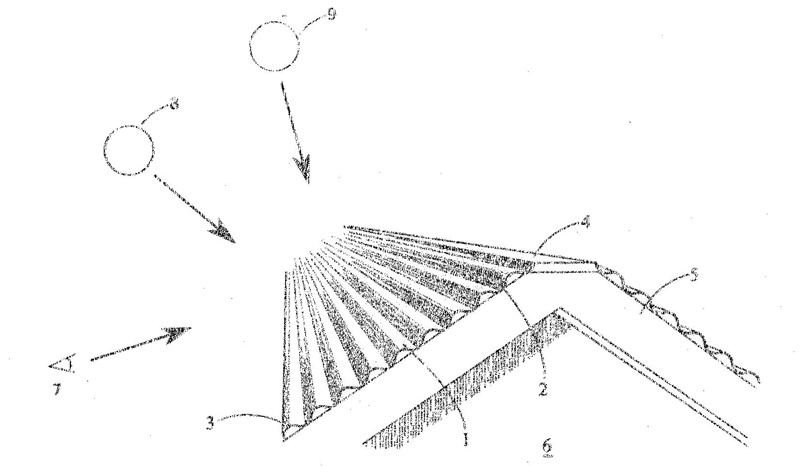
[0032]Embodiments of this invention relate to the exposed outer profile of roofing systems generally for the purposes of energy performance while maintaining ornamental quality and weather resistant functionality. A generally undulating profile of successive corrugations in a roof along the pitch of the roof and extending along the outer surface of the roof generally in the horizontal direction results in portions of the roof of greater visibility by persons at common viewing positions and portions of lesser visibility. Those portions of lesser visibility by persons at common viewing positions are generally more upward facing and comprise a large part of the sun view factor at increasingly higher elevation angles.

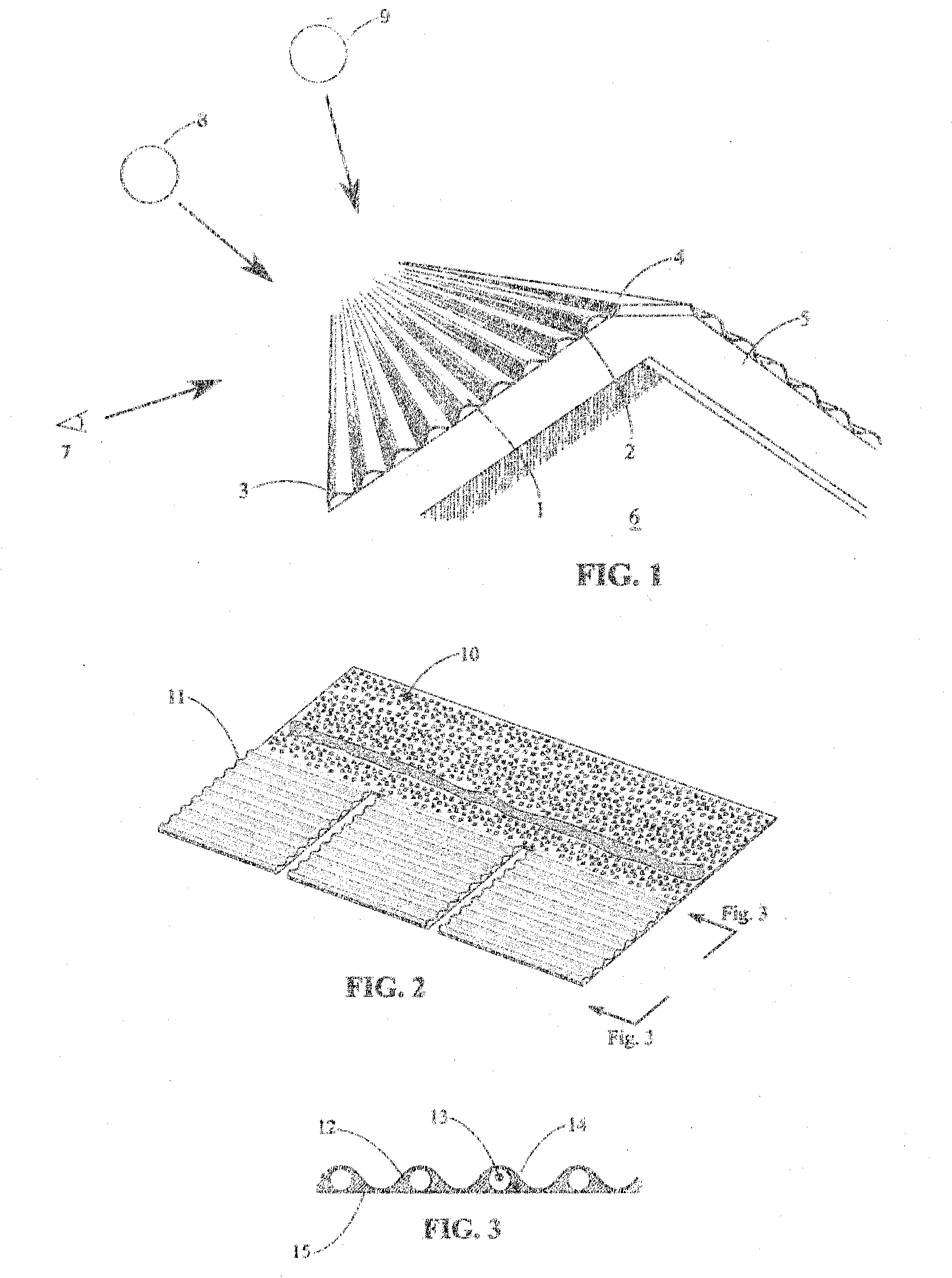
[0033]FIG. 1 illustrates a simple embodiment of a roof according to this invention. The generally undulating shape is shown as a series of corrugated profiles along the pitch of the roof from the fascia (3) to the ridge (4). Each undulating profile has a portion of the expo...


PUM


Abstract

This invention relates to various methods of improving the energy efficiency and utility of roofs typically of the flexible membrane granulated type including shingles and roll roofing using a series of generally continuous curved surfaces although is applicable to all types of roofing including metal, concrete, and clay roofing products. Further, this invention relates to a spacer apparatus used to effect several methods of improving the utility and efficiency of roofing of this class.

Description

CROSS REFERENCE TO RELATED APPLICATIONS[0001]I claim priority to U.S. Provisional Application No. 61 / 486,323 filed on May 15, 2011 entitled Undulating Roof Profile for Enhanced Energy Performance and FunctionalitySTATEMENT REGARDING FEDERALLY SPONSORED RESEARCH OR DEVELOPMENT[0002]Not ApplicableTHE NAMES OF THE PARTIES TO A JOINT RESEARCH AGREEMENT[0003]Not ApplicableREFERENCE TO SEQUENCE LISTING, A TABLE OR A COMPUTER PROGRAM LISTING COMPACT DISC APPENDIX[0004]Not ApplicableBACKGROUND OF THE INVENTION[0005]Heat energy transfer through the building envelope changes the temperature of the interior space and can make the space uncomfortable. Energy must be expended to maintain the desired temperature if this space is conditioned in order to offset energy transfer to or from the environment. Therefore, minimal energy transfer across the envelope is desirable. The rate of energy transfer across the building envelope becomes significant when large temperature differences exist between th...

Claims


Application Information

Patent Timeline
IPC IPC(8): E04B7/18B32B3/28B05D1/12
CPCB32B3/28E04D1/04E04D1/26E04D1/28E04D13/103Y10T428/24628F24J2/045F24J2/0455Y02E10/44Y02B10/20Y10T428/24355B32B2419/06F24S20/67F24S20/69Y02E10/40
Inventor BOTKE, MATTHEW MURRAY
Owner BOTKE MATTHEW MURRAY
Why Eureka
Try Eureka