Disc brake apparatus with electric parking mechanism

a technology of disc brake apparatus and electric parking mechanism, which is applied in mechanical apparatus, brake systems, transportation and packaging, etc., can solve the problems of reduced working efficiency of repair, maintenance or assembly of pads to a vehicle, vibration, noise, abnormal wear of both pads, etc., to improve the layout properties, improve the working efficiency of repair and maintenance, and improve the degree of freedom in disposing the electric motor with respect to a radial direction of the worm

a technology of disc brake apparatus and electric parking mechanism, which is applied in mechanical apparatus, brake systems, transportation and packaging, etc., can solve the problems of reduced working efficiency of repair, maintenance or assembly of pads to a vehicle, vibration, noise, abnormal wear of both pads, etc., to improve the layout properties, improve the working efficiency of repair and maintenance, and improve the degree of freedom in disposing the electric motor with respect to a radial direction of the worm

US20120292141A1Inactive Publication Date: 2012-11-22AKEBONO BRAKE IND CO LTD

Image

  • Disc brake apparatus with electric parking mechanism
  • Disc brake apparatus with electric parking mechanism
  • Disc brake apparatus with electric parking mechanism

Examples


first embodiment

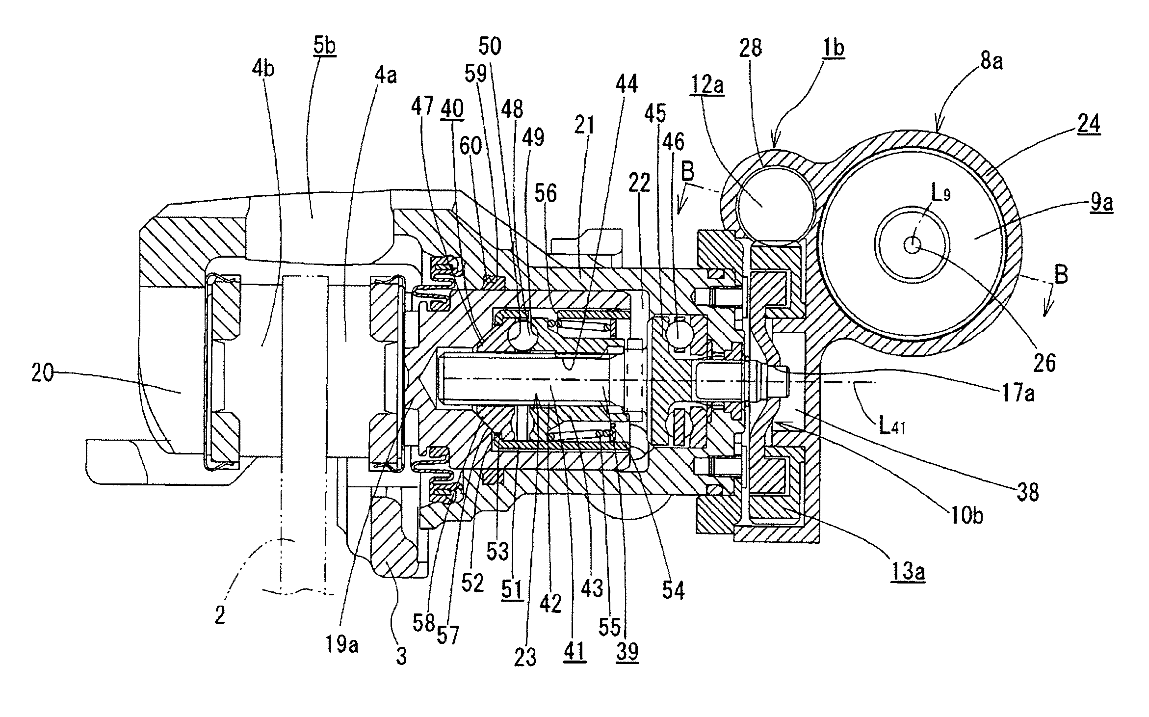
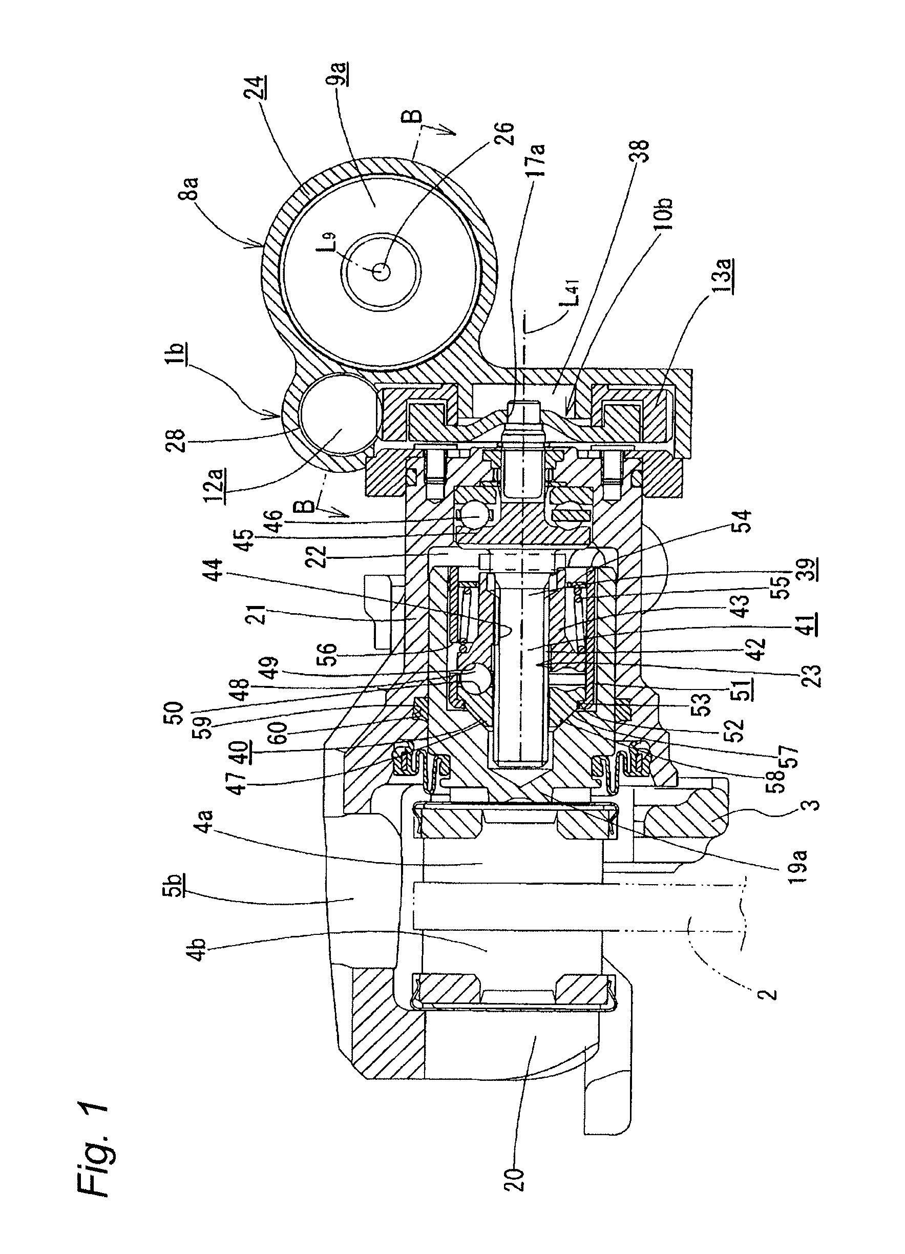
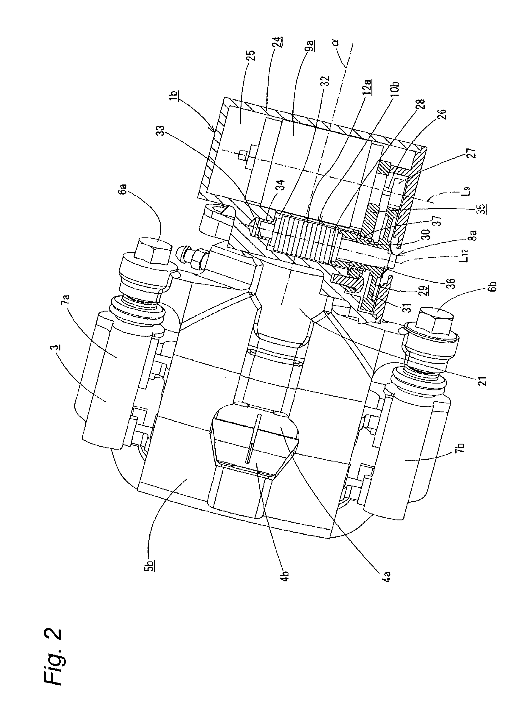
[0055]FIGS. 1 to 4 show the invention. This embodiment illustrates a construction in which the invention is applied to a floating caliper type disc brake apparatus in which a service brake for slowing or stopping a running vehicle is operated hydraulically and a parking brake for holding the vehicle in a stopped state is operated electrically. The construction of a hydraulic service brake system and a basic construction of a parking brake system like those described above are described in PTL 1, and therefore they will briefly be described here.

[0056]In a disc brake apparatus 1b with an electric parking mechanism of a first embodiment, a pair of pads 4a, 4b and a caliper 5b are supported so as to be displaced in an axial direction on a support 3 which is fixed to a vehicle body so as to be disposed adjacent to a rotor 2 which rotates together with a wheel. Because of this, in the embodiment shown in the figures, as with the conventional constructions shown in FIGS. 6 to 9, a pair of...

second embodiment

[0088]FIG. 5 shows the invention.

[0089]In a disc brake apparatus 1c with an electric parking mechanism of this embodiment, an electric motor 9b is disposed above a cylinder portion 21a of a caliper 5b as seen in FIG. 4.

[0090]In the case of the disc brake apparatus 1c with an electric parking mechanism that is configured in the way described above, the position of the center of gravity of the disc brake apparatus 1c in whole can be disposed on the side of a rotor 2. Because of this, a rotational moment that is applied to a support portion of the disc brake apparatus 1c can be reduced, and hence, it is possible to prevent the generation of rattling noise, dragging due to the deterioration in slidability of guide pins 6a, 6b and abnormal wear of brake pads 4a, 4b.

[0091]The second embodiment is similar to the first embodiment that has been described above except that the electric motor 9b is disposed differently, and therefore, the illustration and description of like portions will be ...


PUM


Abstract

An electric thrusting unit for a disc brake with an electric parking mechanism includes a worm reduction gear and a thrust generation mechanism. The thrust generation mechanism converts rotational movement transmitted by way of the worm reduction gear into linear movement. A worm wheel of the worm reduction gear is supported on the thrust generation mechanism concentrically with a rotational member of the thrust generation mechanism. A drive side gearwheel and a driven side gearwheel are meshed with an output shaft of the electric motor directly or by way of an additional gearwheel so as to transmit a rotational force of the output shaft to the worm. The drive side gearwheel is provided concentrically with the output shaft and so as to rotate together therewith. The driven side gearwheel is provided on a part of the worm concentrically with the worm and so as to rotate together therewith.

Description

TECHNICAL FIELD[0001]The present invention is related to an improvement in a disc brake apparatus with an electric parking mechanism in which a braking force is generated using an electric motor as a drive source and moreover, the braking force can be kept applied even after the energization to the electric motor is stopped.BACKGROUND ART[0002]Conventionally, as electric disc brakes, there have been proposed various types of electric disc brakes having a construction in which an output of an electric motor is inputted into a booster mechanism, the rotational movement of the electric motor is converted into linear movement while being boosted by the booster mechanism, and a pair of pads are pressed strongly against both sides of a rotor.[0003]Additionally, there also conventionally have been known various types of electric disc brake apparatuses in which an electric parking mechanism in which a braking force can be kept applied even after the energization to an electric motor is stop...

Claims


Application Information

Patent Timeline
22 Nov 2012
Publication
US20120292141A1
IPC
B60T13/74; B60T1/06; F16D65/18
CPC
F16D65/18; F16D2121/24; F16D2125/36; B60T13/741; F16D2125/48; F16D2125/52; F16D2125/40
Inventors
TAKAHASHI, KIMIO