Mass flow increase at takeoff in supersonic airliner

a supersonic airliner and mass flow technology, applied in the field of supersonic aircraft, can solve the problems of reducing the jet velocity out of the exhaust nozzle, and achieve the effects of reducing noise, and reducing the pressure in the jet pip

Inactive Publication Date: 2012-11-22
KOSHELEFF PATRICK A
View PDF6 Cites 18 Cited by
  • Summary
  • Abstract
  • Description
  • Claims
  • Application Information

AI Technical Summary

Benefits of technology

[0010]For takeoff, the wedge folds closed to admit intake air to the front fan, and hinged panels ahead of the rear fan swing open to capture the airflow for the rear fan. Clutches at the front of the turbojet engage, turning the driveshafts which extend forward to pinions in mesh with a central gear. The gear is on a shaft carrying the remote fans, which turn. They discharge lightly compressed air below the nacelle in a backward direction to produce forward thrust with relatively low noise.
[0011]The energy to drive the remote fans is taken from the turbojet cycle. The exhaust nozzles are opened wider than for greatest exhaust jet velocity. The pressures in the jet pipes are reduced. The turbojets's turbines expand the working gas more than usual, generating extra shaft work. That work turns the remote fans. As a further consequence, the reduced pressure in the jet pipe causes decreased jet velocity out of the exhaust nozzles. That reduces jet noise at takeoff too.

Problems solved by technology

As a further consequence, the reduced pressure in the jet pipe causes decreased jet velocity out of the exhaust nozzles.

Method used


Image

  • Mass flow increase at takeoff in supersonic airliner
  • Mass flow increase at takeoff in supersonic airliner
  • Mass flow increase at takeoff in supersonic airliner

Examples


Embodiment Construction

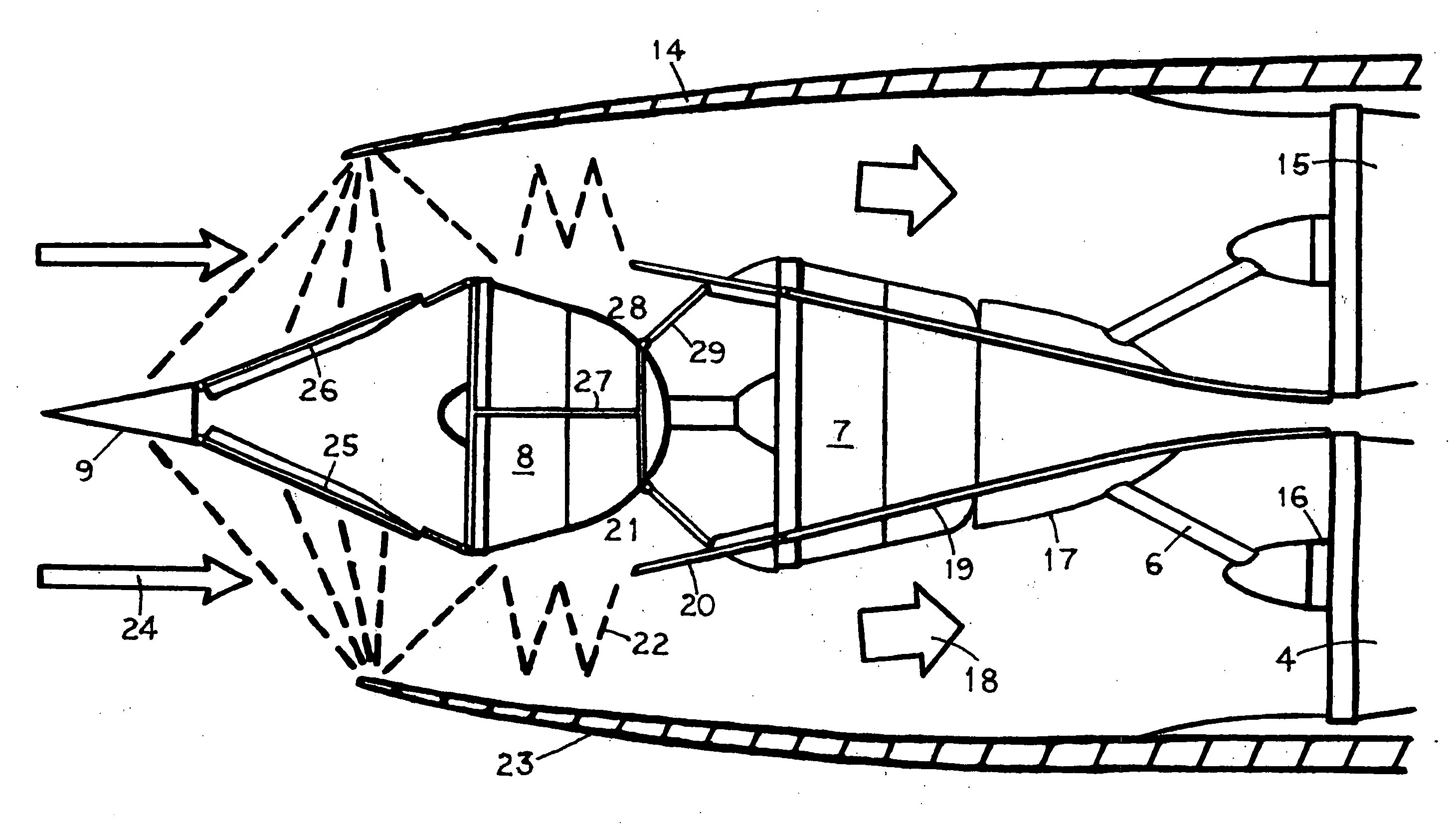
[0024]This document applies to a supersonic airliner powered by turbojet engines. Turbojet engines provide efficient thrust at Mach 2 cruise, but are very noisy at takeoff because the jet exhaust velocity is high. A solution known in the art is to transfer some energy out of the turbojet cycle at takeoff an order to power a remote fan. The fan output is discharged for thrust independent of the turbojet. Total air mass flow can be doubled, while the turbojet's exhaust jet velocity is decreased. The net thrust stays the same, but the noise is reduced.

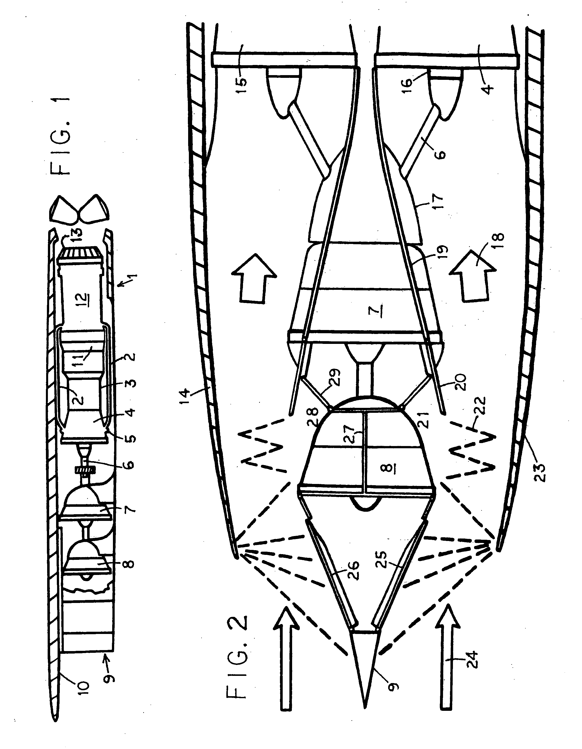
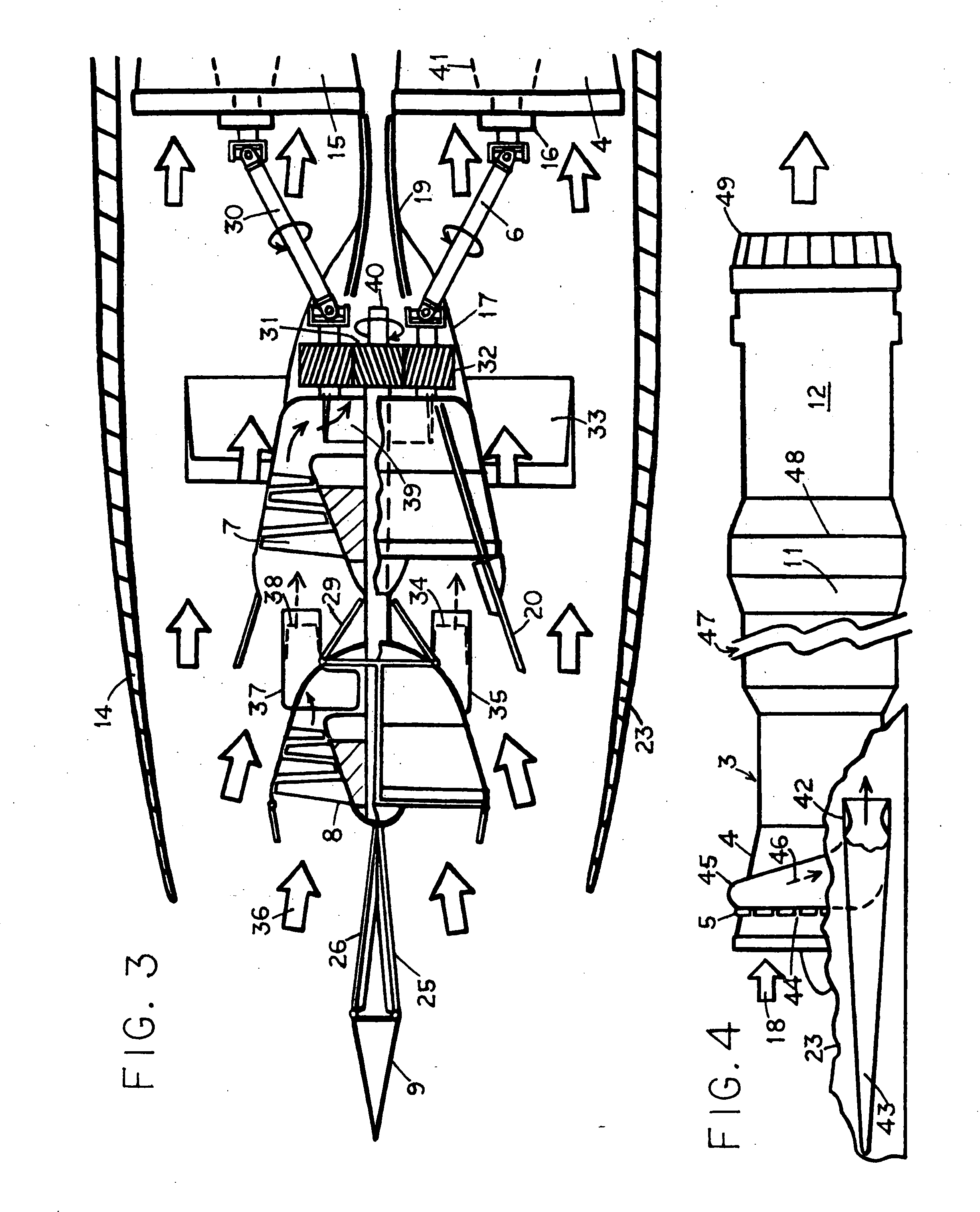
[0025]The invention is concerned with the engine nacelles and their contents. Each nacelle houses two turbojet engines. FIG. 1 is a side view of such a nacelle 1 with its side wall broken away to show the contents. Two-spool turbojet 3 is visible, with its low pressure (“LP”) compressor 4 in front. Nacelle 1 is inspired by the example of the Concorde Mach 2 airliner because nacelle 1 similarly hangs below wing 10 seen in cross section. Th...


PUM


Abstract

In a supersonic aircraft, turbojet engine nacelles each containing two remote fans in the front half of the nacelle, for noise reduction at takeoff. During supersonic flight, a front wedge at the nacelle nose achieves external compression of intake air. The wedge is vertical, sending the airflow left and right inside the nacelle along its side walls. The two flows follow mirror image curved paths on their way to a turbojet, leaving unused space between them to house the fans in tandem. For takeoff, clutches connected to the turbojets's compressors are engaged. Driveshafts turn pinions against a gear on the same shaft as the remote fans. The fan output is discharged backward under the nacelle to produce thrust. The energy to turn the fans is taken from the turbojet cycle. The reduced exhaust jet velocity decreases its noise. Supercharging produces the extra power to turn the remote fans if multistage.

Description

BACKGROUND OF THE INVENTION[0001]In a supersonic aircraft powered by turbojets, remote fans are added ahead of the turbojets and connected to them by driveshafts which take some power from the compressor rotors. This doubles the airflow and decreases the jet exhaust velocity. A remote front fan is known in the art in U.S. Pat. No. 3,161,019. His FIG. 10 shows an auxiliary compressor 62 driven by a shaft 64 controlled by a crutch and connected to a gas turbine engine 15.[0002]The engine nacelle is like the ones in Concorde Mach 2 airliner, a long flat box slung under a wing and containing two turbojets in the rear half. The front half of the nacelle houses the intake air ducts, again like Concorde. However, our nacelle's two intake air ducts are back-to-back, like those in the USAF B-1 bomber. The air ducts curve apart from each other in the middle, therefore that space is where the remote fans are housed.[0003]In the B-1, the air intakes start with wedge-shaped external-shock inlets...

Claims


Application Information

Patent Timeline
Patent Type & Authority Applications(United States)
IPC IPC(8): B64D33/02B64C1/40
CPCB64C30/00B64D33/02F01D15/00F02K3/02F02K3/075Y02T50/672F02C7/042F02C9/18F05D2260/4031F05D2260/40311B64D2033/026F02K3/077Y02T50/60
Inventor KOSHELEFF, PATRICK A.
Owner KOSHELEFF PATRICK A
Why Eureka
Try Eureka