Method of in situ calibrating load sensors of a wind turbine blade

a technology of load sensor and wind turbine blade, which is applied in the direction of motors, engine control, wind energy generation, etc., can solve the problems of aging or possible damage of the blade, and achieve the effect of less time-consuming and further precision in the calibration process

Active Publication Date: 2012-11-22
LM GLASSFIBER
View PDF7 Cites 39 Cited by
  • Summary
  • Abstract
  • Description
  • Claims
  • Application Information

AI Technical Summary

Benefits of technology

[0010]The advantage of the present concept is that it is possible to calibrate the sensors on-site while the blades are mounted on the turbine, i.e. without needing to dismount the blades from the turbine. The calibration may be performed while the turbine is running and connected to the grid. A system is continuously logging the relevant data (turbine operating conditions and sensor measurements), and after some time it has collected enough data to be able to do a reliable calibration of the sensors. The calibration is done fully automatic. There is no special calibration procedure, i.e. there is no requirement for human interaction or carrying out special maneuvers with the turbine. All data are collected during normal operation of the turbine. However, most of the useful data will be collected mainly in situations where the turbine is idling at low wind speeds and during startup of the turbine. These operational situations occur relatively often, so it is just a matter of time before the system has collected enough data to do the calibration. When the system is continuously re-calibrating the sensors, it is possible to detect sudden chances in the calibration values that could indicate changes in the bending stiffness. This could reveal aging or a possible damage of the blade.
[0011]By calculating a theoretical load for each sample based on both the rotor azimuth angle and the pitch angle of the blade, the need for keeping one of the two parameters fixed is alleviated, and both parameters may change between samples. Compared to for instance EP2112375 and DE102006036157, this means that the calibration of the sensors can be carried out continuously and does not have to go through a special calibration process. Calibration samples may instead be automatically collected when the wind turbine conditions are within given parameters. Also, the auto calibration method according to the present invention may be carried out more precisely, since each sample is compared to a separately calculated theoretical load, in which multiple parameters may be taken into account. The prior art calibration methods instead rely on simplified conditions, where a sinusoidal data can be extracted from pitch cycles or rotor cycles. Such data will seldomly be true sinusoidal in practice.
[0017]In one advantageous embodiment, the first cross-section comprises at least two load sensors. Thereby, it is possible to deduct flapwise and edgewise bending moments by superposition, even if the two sensors are not located on the exact bending axes. The at least two load sensors may comprise a first load sensor located near a trailing edge of the first wind turbine blade, and a second load sensor located between a leading edge and the trailing edge of the first wind turbine at a suction side or a pressure side of the first wind turbine blade. This provides an advantageous embodiment, where the first load sensor and the second load sensor are located near the first principal bending axis and the second principal bending axis of the blade, respectively. According to another embodiment the one or both of the at least two load sensors are located on principal bending axes of the blade.
[0018]According to another embodiment, the first wind turbine blade further is provided with a number of second load sensors positioned in a second cross-section of the first wind turbine blade. The same calibration steps as performed for the calibration of the first load sensors should be carried out for the calibration of the second load sensors as well. The first wind turbine may comprise load sensors only in 1 to 5 different cross-sections, advantageously only 1 to 4 different cross sections, and more advantageously only 1 to 3 different cross-sections. The first wind turbine blade may even comprise load sensors in only 1-2 different cross-sections. Thus, measurements and calibration are carried out only for a small number of load sensors, which overall reduces the computational complexity of the system.
[0020]According to another advantageous embodiment, the calculations of step d) are further based on inertia forces and / or inertia moments from rotation of the rotor. Such additional factors add further precision to the calibration process. The inertia forces may advantageously be based on centrifugal forces and / or Coriolis forces and / or forces due to rotor acceleration. In addition, it may be possible to add inertia forces due to yawing of the wind turbine to the calculations. This adds even further precision to the calibration process.
[0022]Even more, the calculations of step d) may advantageously further be based on general properties of the first wind turbine blade and a part of the first wind turbine blade located at outboard of the first cross-section. Thus, the outboard part comprises the part of the blade located between the first cross-section and the blade tip. The general properties may be based on one or more of the following parameters: mass, mass moment, moment of inertia and product of inertia. Once these general properties are calculated, the rest of the calculations can be executed linearly and are much less time-consuming, because the iteration through all the blade sections are avoided. This innovative approach enables a real time calculation without requiring excessive computational capacity. This means that the measurements can be processed immediately after each sample, and the calibration can run continuously, i.e. in real-time.

Problems solved by technology

These operational situations occur relatively often, so it is just a matter of time before the system has collected enough data to do the calibration.
This could reveal aging or a possible damage of the blade.

Method used


Image

  • Method of in situ calibrating load sensors of a wind turbine blade
  • Method of in situ calibrating load sensors of a wind turbine blade
  • Method of in situ calibrating load sensors of a wind turbine blade

Examples


Embodiment Construction

1. Introduction

[0048]New wind turbine blades are increasingly often equipped with load sensors used for control purposes and / or monitoring. In order to obtain reliable measurements, the load sensors must be calibrated. This can be done in the factory, but is relatively costly. If for some reason the load sensors need to be re-calibrated after some operation on the turbine, it would be very expensive to dismount the blades and carry them to the factory for calibration. Therefore, there is a demand for a possibility of calibrating the sensors on-site and preferably while the blade is mounted on the turbine.

[0049]This document describes a concept for fully automatic calibration of the sensors on-site while the turbine is running and connected to the grid. The methods and ideas are described, and the equations needed for implementation in the software for the auto calibration device are presented.

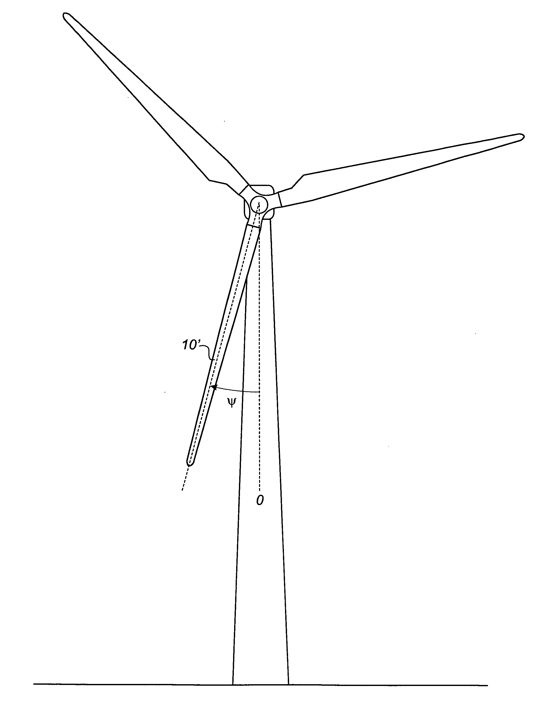
[0050]FIG. 1 illustrates a conventional modern upwind wind turbine according to the so-call...


PUM


Abstract

A method of in situ calibrating load sensors of a horizontal axis wind turbine is described. The method comprises the steps of: a) determining a rotor azimuth angle of a first wind turbine blade, b) determining a pitch angle of the first wind turbine blade, c) measuring loads in a first cross-section of the first wind turbine blade using the first load sensors, d) calculating theoretical loads based on at least the rotor azimuth angle and the pitch angle of the blade determined in steps a) and b), e) comparing the loads measured in step c) with the theoretical loads calculated in step d), and f) calibrating the first load sensors based on the comparison of step e), wherein the calibration are based only on measurements carried out, when the generator is cut out.

Description

TECHNICAL FIELD[0001]The present invention relates to a method of in situ calibrating load sensors of a horizontal axis wind turbine, the wind turbine comprising: a rotor including a hub and a number of wind turbine blades, which extend radially from the hub, the hub being connected to a drive train including a generator, which converts mechanical rotational motion of the rotor into electrical energy, wherein said number of blades comprises at least a first wind turbine blade provided with a number of first load sensors positioned in a first cross-section of the first wind turbine blade.[0002]New wind turbine blades are increasingly often equipped with load sensors used for control purposes and / or monitoring.BACKGROUND[0003]WO08135789 and EP2112375 from the same patent family disclose a method of detecting formation of ice on the blades of a wind turbine, wherein the blades are provided with fibre strain sensors for measuring mechanical strain of the wind turbine blades. The documen...

Claims


Application Information

Patent Timeline
Patent Type & Authority Applications(United States)
IPC IPC(8): H02P9/04F03D9/00
CPCF03D1/065F03D11/0091F05B2270/326Y02E10/722F05B2270/331F05B2270/802Y02E10/721F05B2270/328F03D17/00F05B2270/803Y02E10/72
Inventor SLOT, MARK OLAF
Owner LM GLASSFIBER
Why Eureka
Try Eureka