
Bootstrap gate driver

a gate driver and bootstrap technology, applied in the field of power conversion, can solve the problems of driving loss, conduction loss, switching loss, and body diode loss, and achieve the effect of effective/substantial increase of light-loading efficiency

Active Publication Date: 2012-11-22
SPI ELECTRONICS +1
View PDF12 Cites 35 Cited by
  • Summary
  • Abstract
  • Description
  • Claims
  • Application Information

AI Technical Summary

Benefits of technology

[0023]From the above, in the invention, the provided bootstrap gate driver applied in the synchronous rectification application is capable of inactivating a switching of the high-side transistor and low-side transistor (i.e. synchronous rectification) when the load is in the light-loading state, such that the light-loading efficiency can be effectively / substantially increased. And, the operation of the low-side driving path is not affected by enabling or disabling the high-side driving path.

Problems solved by technology

There are conduction loss, driving loss, switching loss and body diode loss in the operating region of synchronous rectifiers.
When the load is in the heavy-loading state, the load current becomes larger and makes the conduction loss become the main part of loss.
When the load is in the light-loading state, the load current is small, such that the switching loss and driving loss both caused by turning on / off synchronous rectifiers become the main part of loss.
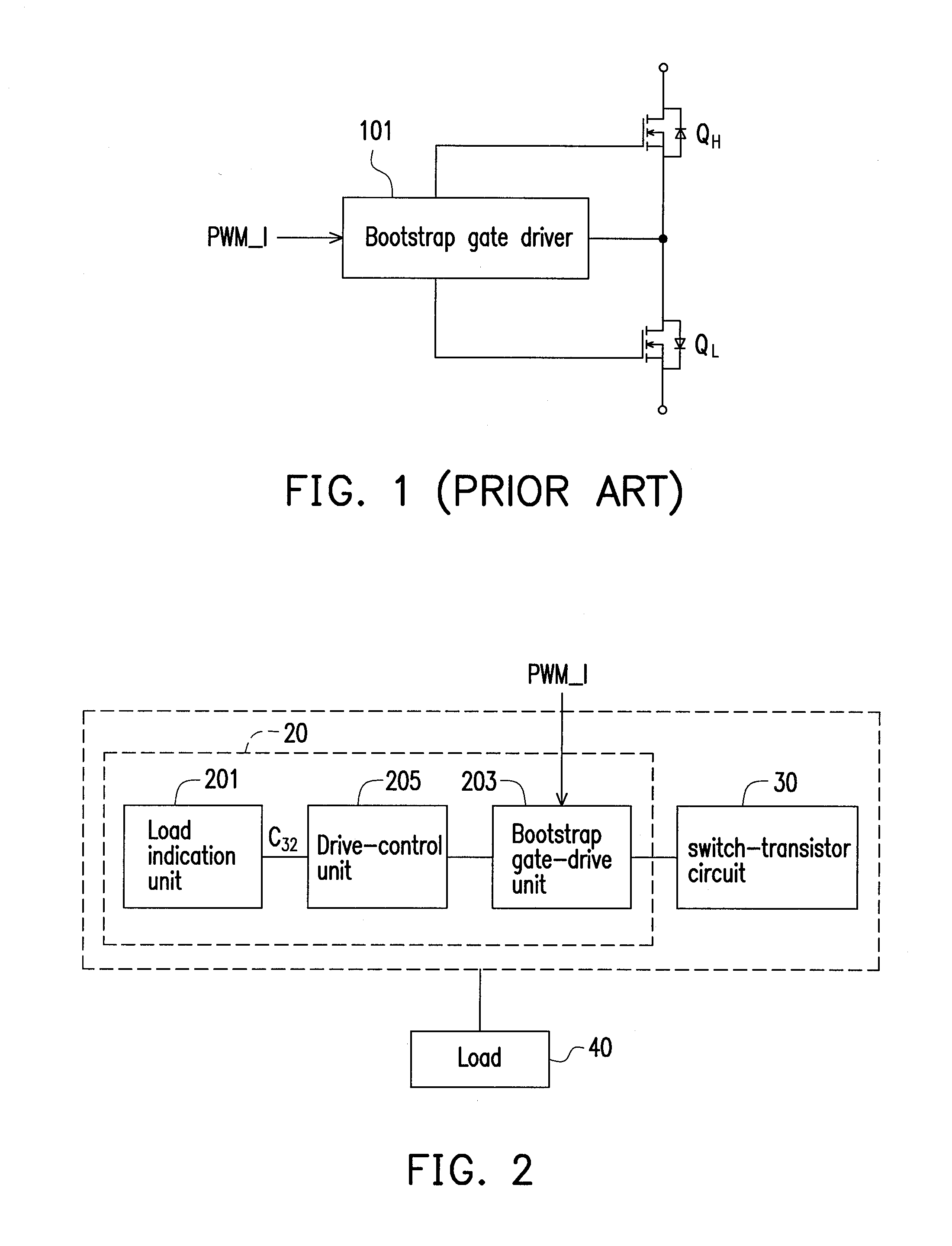
In other words, a switching of the synchronous rectification is still activated when the load is in the light-loading state, such that the light-loading efficiency will not be effectively increased in case that the traditional bootstrap gate driver 101 is applied in the synchronous rectification application.

Method used


Image

  • Bootstrap gate driver
  • Bootstrap gate driver
  • Bootstrap gate driver

Examples


Embodiment Construction

[0032]Reference will now be made in detail to the present preferred embodiments of the invention, examples of which are illustrated in the accompanying drawings. Wherever possible, the same reference numbers are used in the drawings and the description to refer to the same or like parts.

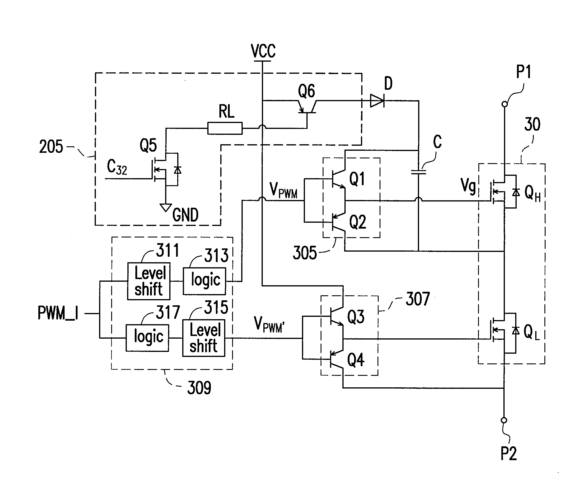
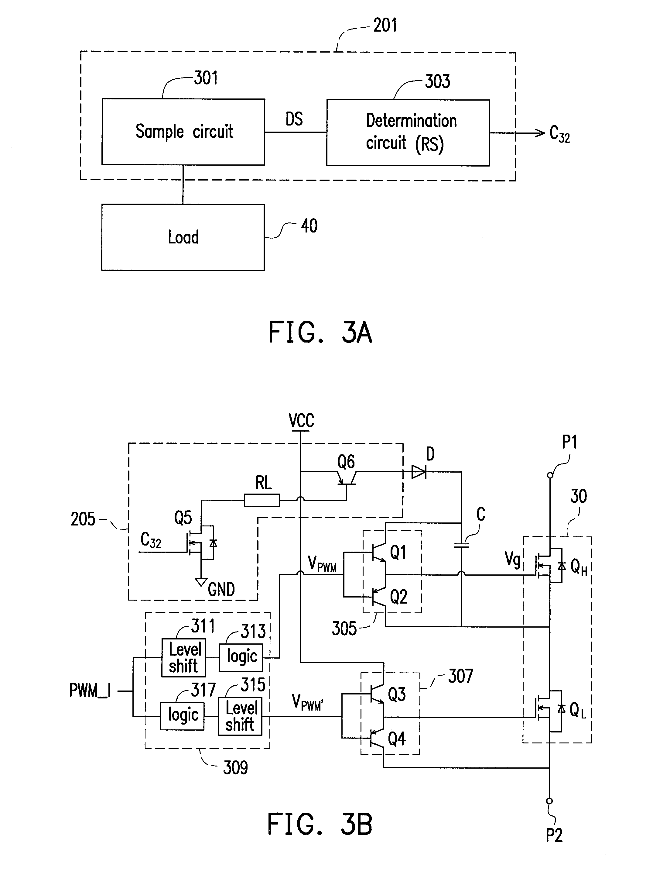
[0033]Based on the demands of high efficiency, reliability and safety of the switching power supply, the invention provides a bootstrap gate driver 20 as shown in FIG. 2. To be specific, FIG. 2 is a diagram of the bootstrap gate driver 20 according to an exemplary embodiment of the invention. Referring to FIG. 2, the bootstrap gate driver 20 includes a load indication unit 201, a bootstrap gate-drive unit 203 and a drive-control unit 205. The load indication unit 201 is configured to generate a load indication signal C32 in response to a state of a load 40 (for example, an electronic device, but not limited thereto), where a level of the load indication signal C32 represents the state of the load 40,...


PUM


Abstract

A bootstrap gate driver including a load indication unit, a bootstrap gate-drive unit and a drive-control unit is provided. The load indication unit is configured to generate a load indication signal in response to a state of a load. The bootstrap gate-drive unit is configured to drive a switch-transistor circuit in response to an inputted pulse-width-modulation (PWM) signal, wherein the switch-transistor circuit has a high-side driving path and a low-side driving path. The drive-control unit is coupled to the load indication unit and the bootstrap gate-drive unit, and configured to enable or disable the high-side driving path in response to the load indication signal. In the invention, the operation of the low-side driving path is not affected by enabling or disabling the high-side driving path.

Description

CROSS-REFERENCE TO RELATED APPLICATION[0001]This application claims the priority benefit of China application serial no. 201120158231.7, filed on May 18, 2011. The entirety of the above-mentioned patent application is hereby incorporated by reference herein and made a part of this specification.BACKGROUND OF THE INVENTION[0002]1. Field of the Invention[0003]The invention generally relates to a power conversion field, in particular, to a bootstrap gate driver applied in a synchronous rectification circuit / application.[0004]2. Description of Related Art[0005]There are two types of rectification strategies in the power conversion field, one type is diode rectification, and the other type is synchronous rectification. Diode rectification is performed based on the conduction of diodes. Synchronous rectification is performed by usually using a gate driving signal to control the operation (i.e. turned on or off) synchronous rectifiers (SRs). Synchronous rectifiers are usually implemented b...

Claims


Application Information

Patent Timeline
IPC IPC(8): H03K3/36
CPCY02B70/1466H02M3/1588Y02B70/10
Inventor BAI, YONG-JIANGCHEN, QIAO-LIANGWANG, NING-BINSUN, JU-LU
Owner SPI ELECTRONICS
Learn More