Liquid ejecting head and liquid ejecting apparatus

a liquid ejector and liquid ejector technology, applied in printing and other directions, can solve the problems of increasing the number of components, affecting the reliability of the assembly process, so as to achieve the effect of improving reliability

Inactive Publication Date: 2012-11-22
SEIKO EPSON CORP
View PDF24 Cites 7 Cited by
  • Summary
  • Abstract
  • Description
  • Claims
  • Application Information

AI Technical Summary

Benefits of technology

[0020]According to this aspect, a liquid ejecting apparatus that prevents a load from being applied locally to the flow channel members and improves the reliability is provided.

Problems solved by technology

Although ink does not leak from the surfaces where the first flow channel and the second flow channel are affixed to each other using the adhesive, there are cases where air bubbles in the ink leak from those surfaces.
However, if a sealing member provided with an atmosphere exposure channel is pinched by the first flow channel member and the second flow channel member, a load will be placed locally on areas of the first flow channel member and the second flow channel member that oppose the region in which the atmosphere exposure channel is provided, resulting in a risk that those areas will deform.
Accordingly, it is necessary to anchor the first flow channel member and the second flow channel member using fastening members such as screws so that a uniform force is applied to the sealing member, which increases the number of components and complicates the assembly process.
Note that this problem is also present in liquid ejecting apparatuses that eject liquids aside from ink.

Method used


Image

  • Liquid ejecting head and liquid ejecting apparatus
  • Liquid ejecting head and liquid ejecting apparatus
  • Liquid ejecting head and liquid ejecting apparatus

Examples


Embodiment Construction

[0031]The invention will be described in detail hereinafter based on an embodiment. Hereinafter, an ink jet recording head will be given as an example of a liquid ejecting head, and may be called simply a “recording head.” Likewise, an ink jet recording apparatus will be given as an example of a liquid ejecting apparatus.

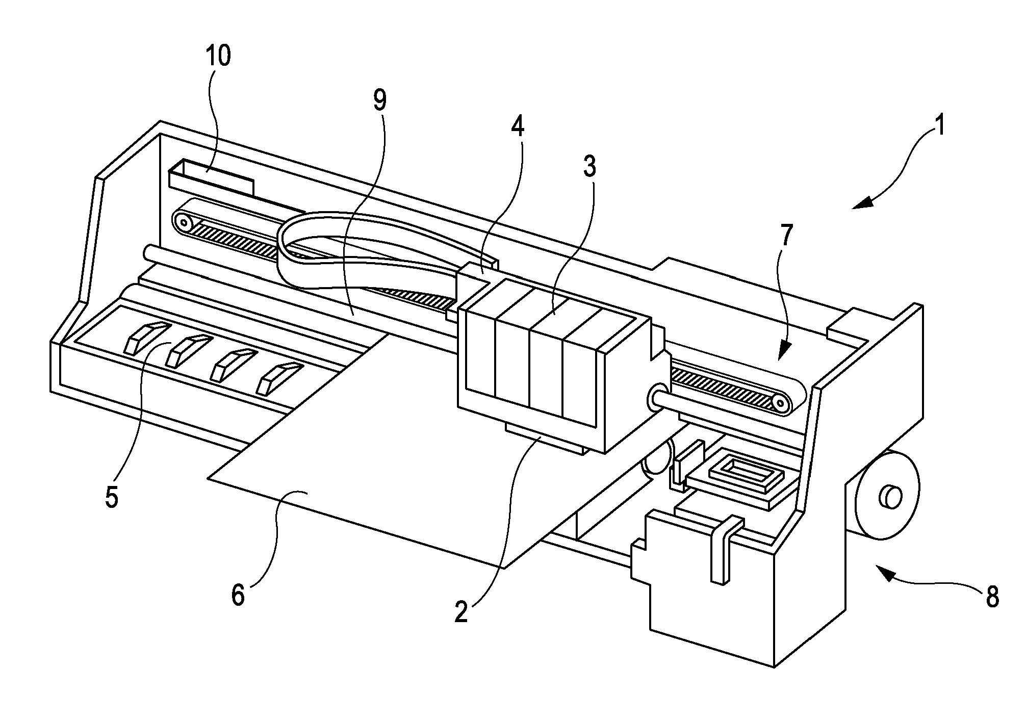
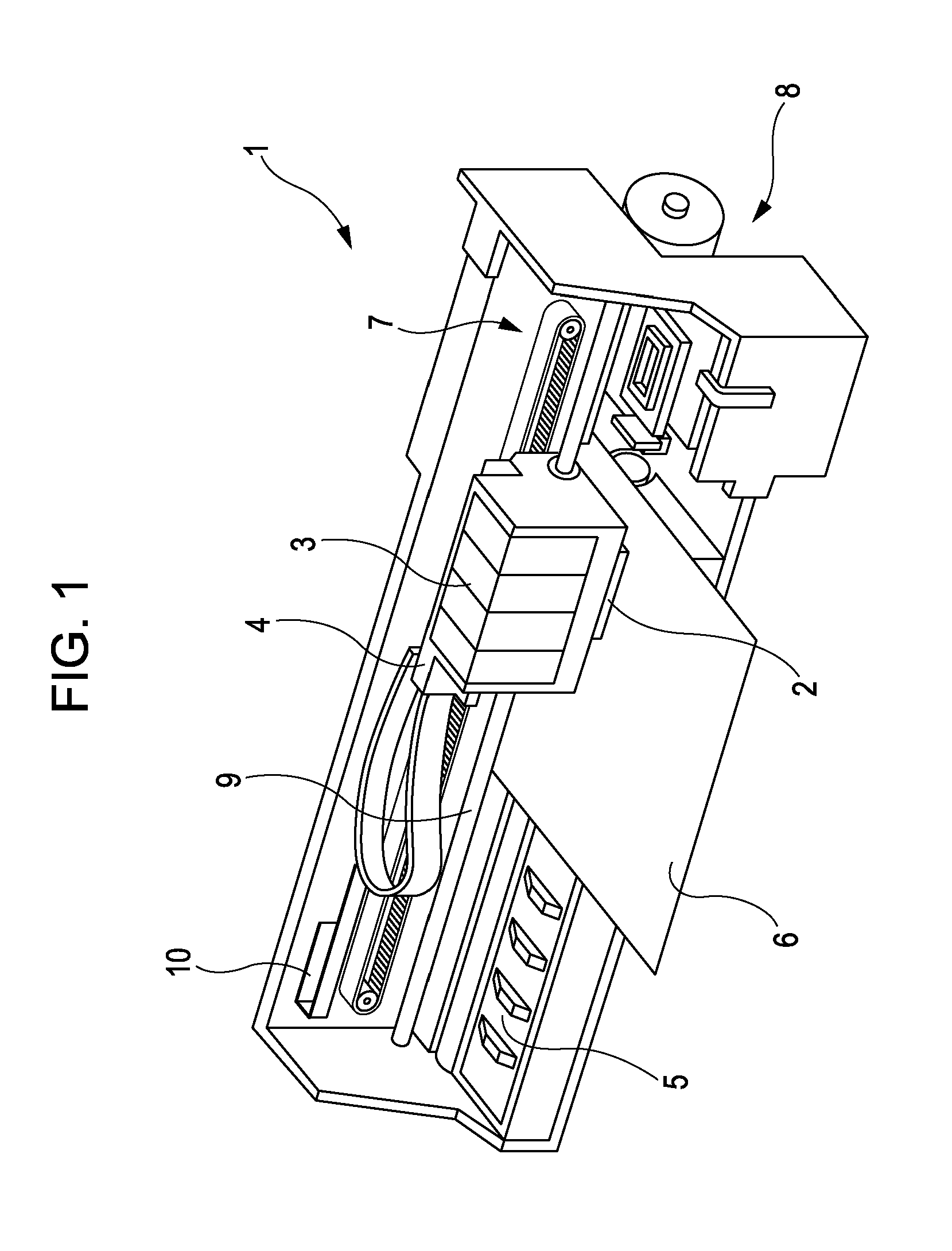
[0032]FIG. 1 is a perspective view illustrating the overall configuration of the ink jet recording apparatus according to this embodiment. An ink jet recording apparatus 1 includes a recording head 2. The recording head 2 is mounted in a carriage 4, and the carriage 4 is provided so as to be capable of moving along a carriage shaft 9.

[0033]Transmitting driving force generated by a driving motor (not shown) to the carriage 4 via a plurality of gears and a timing belt 7 moves the carriage 4, in which the recording head 2 is mounted, along the carriage shaft 9.

[0034]The position of the carriage 4 along the carriage shaft 9 is detected by a linear encoder 10, and detect...


PUM


Abstract

A liquid ejecting head includes: a main head unit that ejects ink; a first flow channel member and a second flow channel member that include first and second flow channels, respectively, through which ink to be supplied to the main head unit flows; and a ring-shaped sealing member pinched by the first flow channel member and the second flow channel member. The first flow channel and the second flow channel communicate with the interior of a space area defined by the first flow channel member, the second flow channel member, and the sealing member, and an atmosphere exposure channel that connects the space area with the exterior is formed in a joining surface between the sealing member and the first flow channel member.

Description

BACKGROUND[0001]1. Technical Field[0002]The present invention relates to liquid ejecting heads and liquid ejecting apparatuses, and particularly relates to ink jet recording heads and ink jet recording apparatuses that eject ink as a liquid.[0003]2. Related Art[0004]An ink jet recording head that ejects ink can be given as a representative example of a liquid ejecting head that ejects a liquid. An ink jet recording head that includes, for example, a plurality of main head units that eject ink through nozzle openings, and a first flow channel member and a second flow channel member provided with a first flow channel and a second flow channel, respectively, for supplying ink to the main head units, where a sealing member is provided between the first flow channel member and the second flow channel member, has been proposed (for example, see JP-A-2011-056872).[0005]The sealing member is pinched by the first flow channel member and the second flow channel member and is compressed to a c...

Claims


Application Information

Patent Timeline
Patent Type & Authority Applications(United States)
IPC IPC(8): B41J2/16B41J2/135
CPCB41J2/17523B41J2/175
Inventor HANAGAMI, TAIKIWATANABE, EIICHIRO
Owner SEIKO EPSON CORP
Why Eureka
Try Eureka