
Modular Switching Network Node for a Communications Network

Active Publication Date: 2012-11-22
SIEMENS AG
View PDF26 Cites 5 Cited by
  • Summary
  • Abstract
  • Description
  • Claims
  • Application Information

AI Technical Summary

Benefits of technology

[0005]It is therefore an object of the present invention to provide a switching network node for a communications network, i.e., an industrial communications network, which can be flexibly adapted to changed or new requirements.
[0018]The switching network node base unit and the port module and the functional module can, for example, be configured such that the port module can easily be swapped for the functional module, i.e., can be easily swapped by a user. This means, for example, that a user can remove the port module from the switching network node base unit in one or a few easy steps and instead likewise place the functional module at this location with one or a few easy steps.
[0019]The simple interchangeability can be provided, for example, by the respective modules being held in the base unit simply by the retaining forces of connected plug-in connections and optionally strain relief by a housing of module and / or base unit. There may also be provision for an additional locking or securing of the port module or of the functional modules against falling out or accidental removal of the module, for example, by a locking mechanism, a screw connection, a catch mechanism or the like. However, in this case the respective module may also be easily removed or inserted in the base unit in a few easy steps, for example, by releasing the screw connection or the locking or catch mechanism.
[0022]Adaptation of the switching network node to different applications may be simplified further in this way because simple interchangeability of modules and therefore simplified adaptation due to incorporation of a functional module, for example instead of a port module, may be attained due to the receiving regions.
[0034]This also results in simplified adaptability of the switching network nodes to changed requirements. As a result of the fact that the base unit can detect a functional module, such as automatically, and can therefore optionally adapt thereto accordingly, integration of the new functionality in the switching network node is simplified. As described above, detection and / or configuration of a new functional module introduced into a module-receiving region can occur, for example, automatically by way of the switching network node base unit or also, for example, following an activation step by a user by way of the switching network node base unit.
[0043]In an advantageous embodiment, the functional module comprises, for example, an additional processing unit or central unit, in particular for supporting a central control unit of the switching network node, or includes such a processing unit or central unit. In this way, for example, the computing power or performance of the switching network node can be increased further and thus optionally adapted to changed performance requirements. By a coupling of such a functional module through the system bus to the central unit of the switching network node, the pending work may then be distributed among these components and the performance of the switching network node thus increased.

Problems solved by technology

One drawback of the prior art switching nodes is that, although the number and / or type of communication interfaces may be changed in this way, such a switch cannot be flexibly adapted to new applications or communication protocols, because the underlying properties of the switch remain unchanged even when a port module is changed.

Method used


Image

  • Modular Switching Network Node for a Communications Network
  • Modular Switching Network Node for a Communications Network

Examples


Embodiment Construction

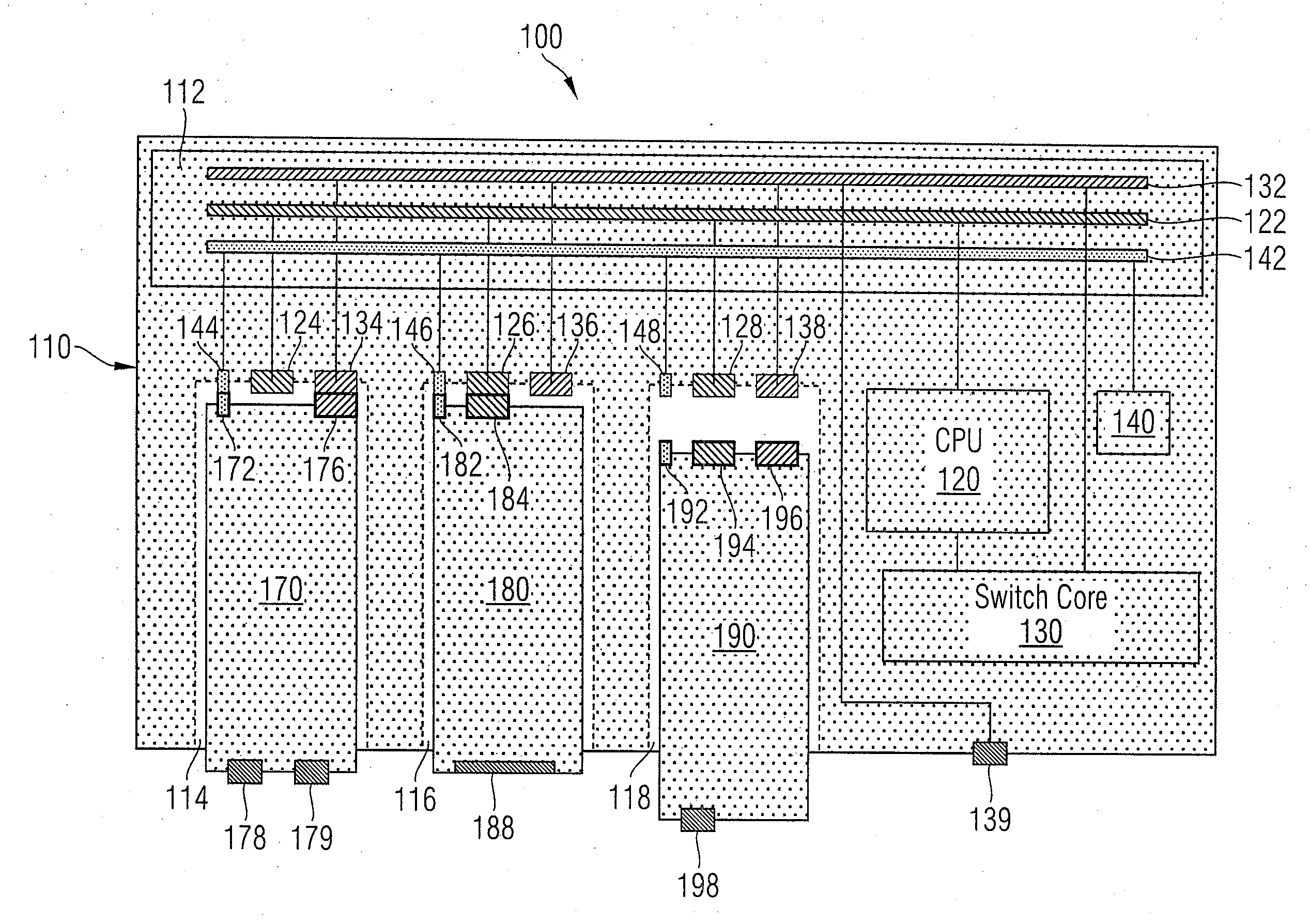
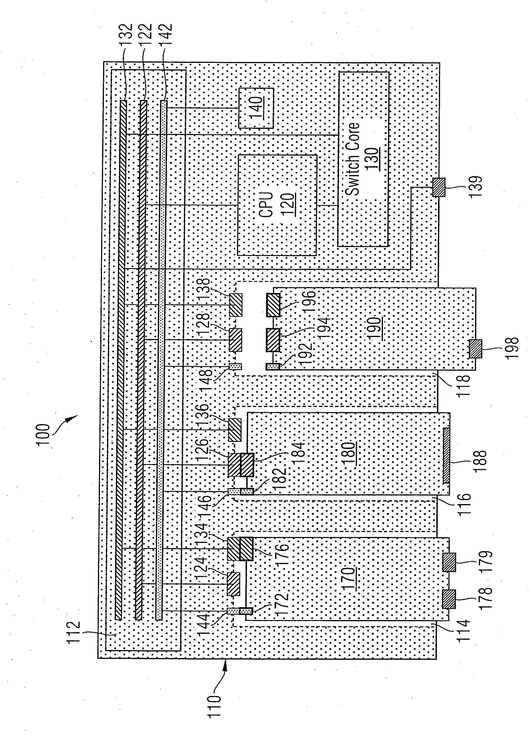
[0057]FIG. 1 shows an Ethernet switch 100 consisting of a base unit 110, a port module 170 inserted therein, a functional module 180 inserted therein and a combined functional port module 190.

[0058]The base unit comprises what is known as a backplane 112, comprising a Peripheral Component Interconnect (PCI) express system bus (PCIe bus) 122, an internal high-speed network bus 132 and a power supply bus 142. The power supply bus 142 is connected to a power supply unit 140 while the PCI express (PCIe) bus 122 is connected to a central processing unit (CPU) 120 of the base unit 110 and the high-speed network bus 132 is connected to a central data forwarding function block 130 (switch core). The CPU 120 is, moreover, also connected to the switch core 130, for example, for operation or configuration of the switch core 130.

[0059]The base unit 110 comprises a first module slot 114 in which the port module 170 is installed. A PCIe plug 124, a network plug 134 and a power supply plug 144 are...


PUM


Abstract

A modular switching network node for a communications network, i.e., an industrial communications network, where the modular switching network node comprises a switching network node base unit and at least one port module, the at least one port module comprises at least one connection interface for coupling to the communications network, and where the modular switching network node is configured to forward communication data over one of the connection interfaces of the modular switching network node to at least one additional connection interface of the modular switching network node. The switching network node base unit is configured such that at least one of the port modules is swappable for a functional module to expand the functionality of the switching network node.

Description

BACKGROUND OF THE INVENTION[0001]1. Field of the Invention[0002]The present invention relates to switching nodes and, more particularly, to a modular switching network node for a communications network, i.e., an industrial communications network, where the modular switching network node comprises a switching network node base unit and at least one port module, and where the at least one port module comprises at least one connection interface for coupling to a communications network, and the modular switching network node is configured to forward communication data through a connection interface of the modular switching network node to at least another of the connection interfaces of the modular switching network node.[0003]2. Description of the Related Art[0004]Switching network nodes are known from the prior art. For example, U.S. Pat. No. 7,085,875 B1 discloses a modular switch for an Ethernet and / or an ATM network with plug-in cards that each comprise ports for such networks or i...

Claims


Application Information

Patent Timeline
IPC IPC(8): H04L29/10H04L12/26H04L12/28H04L12/56
CPCH05K7/1472H04L49/351
Inventor HACK, HEIKOKISTNER, TIMOSCHWEIZER, URSSCHAFFLER, ANDREASWAGNER, MICHAEL
Owner SIEMENS AG
Learn More