Device for removing fluids from vials

a technology for fluid removal and vials, which is applied in the field of fluid removal devices, can solve the problems of similar problems posed in other pharmaceutical or chemical systems comprising two or more components, gas, in particular oxygen from the air, can diffuse through the walls of the applicator or through seals, chemically modify the content, etc., and achieve the effect of reducing the dead volum

Inactive Publication Date: 2012-11-29
MEDMIX SYST
View PDF2 Cites 64 Cited by
  • Summary
  • Abstract
  • Description
  • Claims
  • Application Information

AI Technical Summary

Benefits of technology

[0011]In accordance with a first aspect the present invention provides an adapter-like device which allows a fluid to be removed from a container, wherein the fluid is diverted in the device, e.g. in order to fill a reservoir of an applicator with a fluid from at least one container, the device having a reduced dead volume.
[0013]A device for removing a fluid from at least one container is thus set out. The device comprises a basic body with an upper side and an underside, in which a fluid channel with a constant or variable cross-section is formed along a longitudinal direction. On the upper side of the basic body there is at least one inlet opening, running at an angle (i.e. an angle not equal to 0°, preferred angle >30°, particularly preferred perpendicular) to the fluid channel and opening into the fluid channel, and on the underside of the basic body there is at least one outlet opening, running at an angle (preferred angle >30°, particularly preferred perpendicular) to the fluid channel and also opening into the fluid channel. In relation to the longitudinal direction the outlet opening is arranged offset to the inlet opening, i.e. the outlet opening and the inlet opening open out at different points along the fluid channel. The device also comprises a container connector for connecting a container with the inlet opening, which can be done in any desired manner. In order to reduce the dead volume, in the basic body an insert opening running in the longitudinal direction is formed which opens into the fluid channel, and an insert element is inserted through the insert opening into the fluid channel. This insert element extends along the fluid channel in such a way that in the area between the inlet opening and outlet opening it reduces the cross-section of the fluid channel.
[0019]In a preferred embodiment the fluid channel and the insert element are of complementary shape and conically widen at least in sections (preferably at least in the section between the inlet opening and the outlet opening) towards the insert opening. This very easily achieves the desired sealing effect between the circumferential surface of the insert element and the defining wall of the fluid channel, even in the presence of dimensional tolerances.
[0023]More particularly the device can be designed for the simultaneous removal of fluids from at least two containers. For this the above features are each at least doubly present. In the case of two containers the two fluid channels preferably run collinearly behind one another in the longitudinal direction, and the insert elements are inserted into the two fluid channels from two opposite sides. In other words, in such cases, in the basic body a second longitudinally running fluid channel with a constant or variable cross-section is provided, on the upper side of the basic body a second inlet opening is formed running at an angle to the second fluid channel and opening into the second fluid channel, and on the underside of the basic body a second outlet opening is formed running at an angle to the second fluid channel and opening into the second fluid channel offset in the longitudinal direction to the second inlet opening. The device then has a second container connector to connect a second container to the second inlet opening. In the basic body, running in the longitudinal direction, the second inlet opening is provided facing away from the first inlet opening and opening into the second fluid channel, and the filling device has a second insert element, which is inserted through the second insert opening into the second fluid channel and reduces the cross section of the second fluid channel between the second inlet opening and the second outlet opening.
[0031]Each of the catch structures is preferably designed as follows: the container holder has a preferably at least partially cylindrical jacket wall. The first catch structure and the second catch structure each have a spring arm formed in the jacket wall, at the free end of which a catch lug is formed extending into the interior of the jacket wall. This allows very simple and cost-effective production. The catch structures are preferably offset, more particularly offset by approx. 180° with regard to the circumferential direction of the jacket wall, i.e. they are diametrically opposite each other in order to take up as little space as possible with as great stability of the container holder as possible.

Problems solved by technology

Similar problems are posed in other pharmaceutical or chemical systems comprising two or more components which are not stable in the mixed state.
However, it is often problematical to store flowable substances for a longer period in plastic applicators, as on the one hand the substances can chemically react with the plastic, and on the other hand there is a risk that gas, in particular oxygen from the air, can diffuse though the walls of the applicator or through seals and chemically modify the content.
The drawback of this is that the syringes have to be fitted with such an adapter or needles and necessarily require a certain distance which is predetermined by the diameter and distance of the vials.
However, the design of such a filling device is relative complicated: the device comprises two separately designed housing halves, which have to be connected to each other in order to form the connection area and the hood.
This results in a relative complicated manufacturing process and corresponding increased costs.
In addition the dead volume of such a device is relatively large.
This design requires a very precise fit and alignment of the two housing sections and is susceptible to defects.
This filling device also has a relative large dead volume.
However, known devices are generally not suitable for storing the vials directly on the device, as the accidental puncturing of the septum of a vial during transportation or handling cannot be ruled out.

Method used


Image

  • Device for removing fluids from vials
  • Device for removing fluids from vials
  • Device for removing fluids from vials

Examples


Embodiment Construction

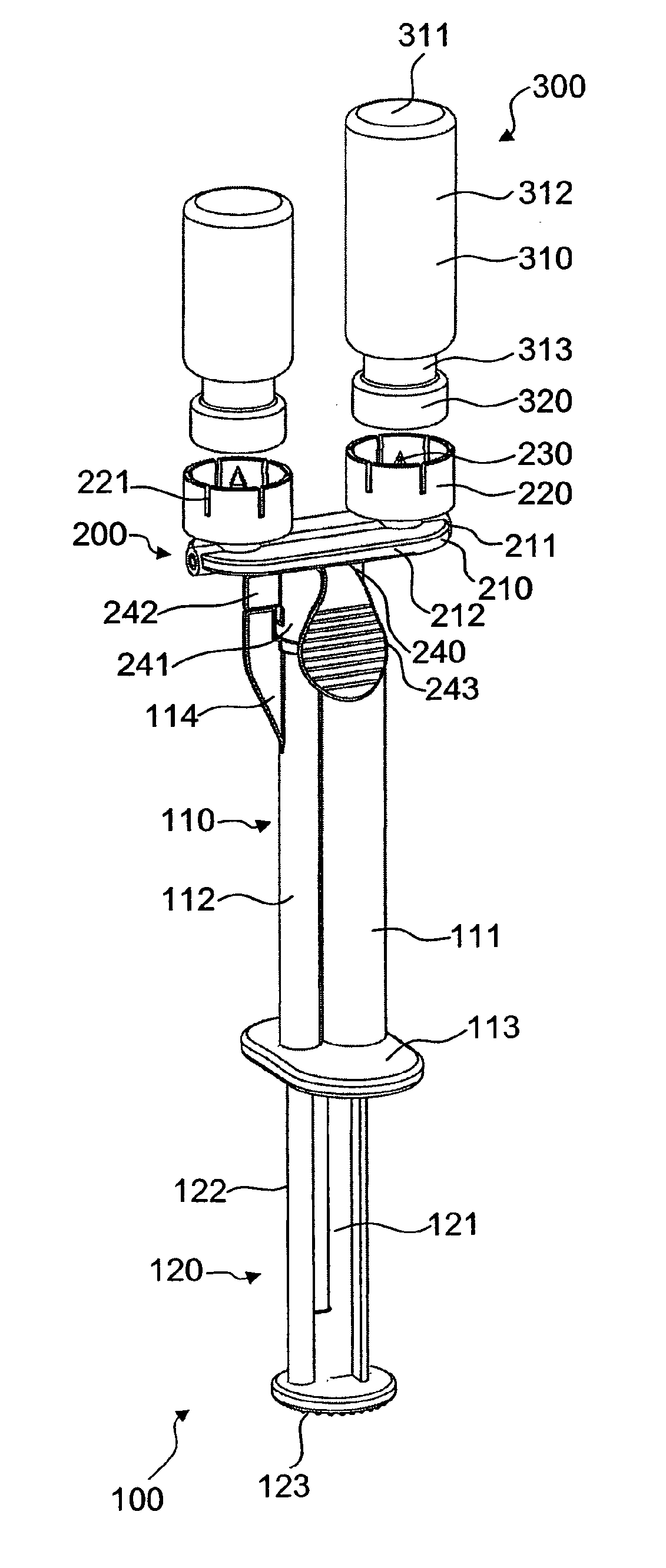
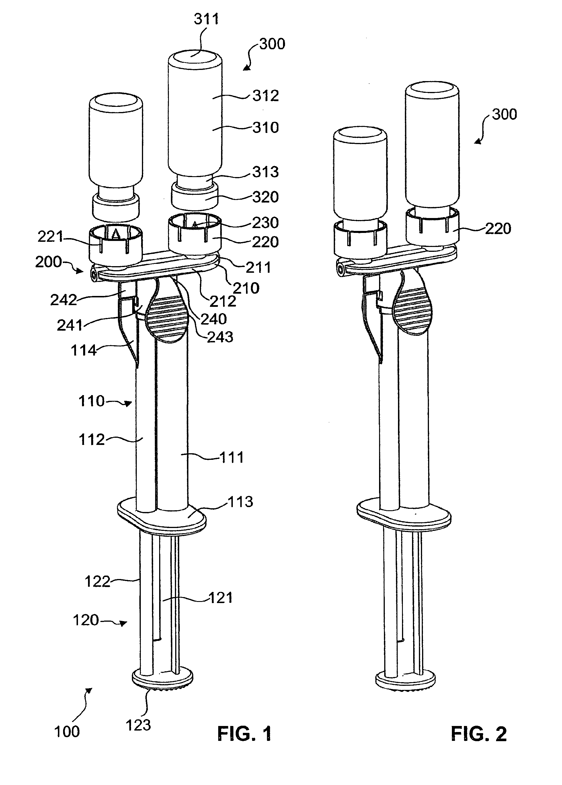
[0045]In FIGS. 1 to 5 a first exemplary embodiment of a filling device in accordance with the invention is illustrated. The filling device 200 has a basic body 210 which is of an elongated, essentially disk-shaped form. Formed on the basic body 210 is a central, cylindrical thickening 211, to which the two halves of a flat carrier plate 212 are connected. With its cylindrical axis the thickening 211 defines a longitudinal direction.

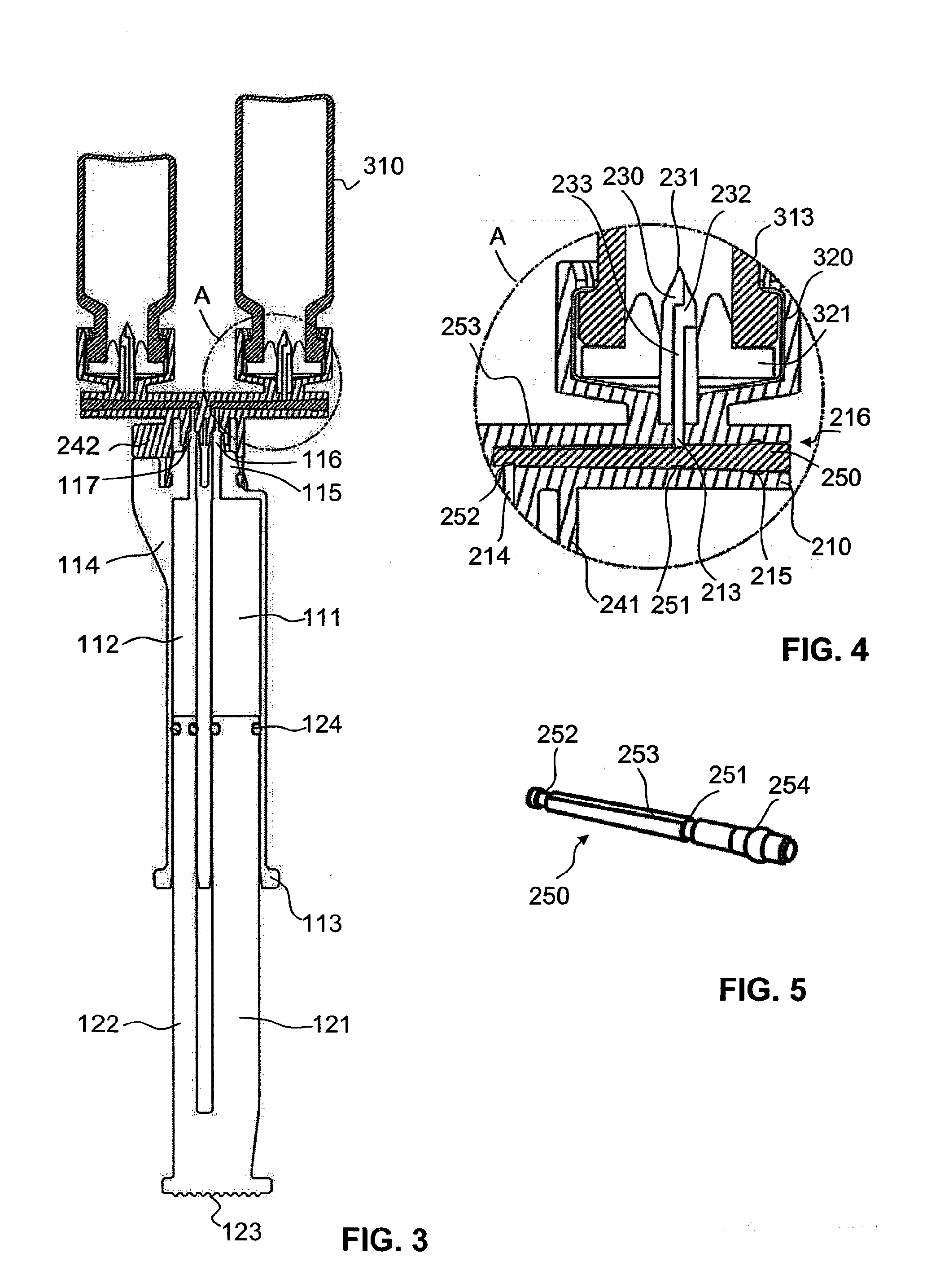
[0046]Along this longitudinal direction from each of the two ends of the cylindrical thickening 211 a blind-type longitudinal bore is formed, which each ends just before the middle of the thickening (FIGS. 3 and 4). Each of these bores widens slightly conically towards its open end and forms a fluid channel. The two bores are collinear to each other, i.e. they are on the same axis one behind the other.

[0047]Toward the upper side of the basic body 210 in the area of the thickening there is an inlet opening 213 for each of the bores (FIG. 4). This inlet ope...


PUM

PropertyMeasurementUnit
angleaaaaaaaaaa
angleaaaaaaaaaa
angleaaaaaaaaaa

Abstract

The invention relates to a device for removing a fluid from at least one container (300), for example, from a vial, that has a seal that can be punctured. The device comprises a base body (210), in which a fluid channel is formed. In order to reduce the lost volume, a pin-shaped insertion element (250) that reduces the cross-section of the fluid channel is inserted into the fluid channel through an insertion opening. Locking structures (262, 263) that retain the container on the device in a removal position and in a storage position different therefrom can be provided so that the container can be stored on the device without the seal being punctured accidentally. Such a device can be used in particular to fill an applicator (100) having one or more fluid reservoirs from one or more vials.

Description

TECHNICAL FIELD[0001]The present invention relates to a device for removing a fluid from at least one container, more particularly from a container closed by means of a seal that can be punctured, e.g. a vial with a septum seal. In particular the invention relates to a device for filling an applicator with at least one fluid reservoir from one or more vials.PRIOR ART[0002]In many applications a mixture of two or more flowable components has to be produced and delivered at a predetermined mixing ratio. An example is the production of an adhesive for technical or medical applications, e.g. a fibrin-based medical adhesive. Another example is the production of a bone cement from several components using a monomer. There are also medicinal products, for example, which are produced by mixing two or more components, but are not storable when mixed. In this case it is desirable to initially store the components separately and only to mix them immediately before their administration. Similar...

Claims


Application Information

Patent Timeline
Patent Type & Authority Applications(United States)
IPC IPC(8): A61J1/20
CPCA61J1/2096A61J2001/2013A61J2001/2058A61J2001/2055A61J2001/2051A61J1/201A61J1/2013A61J1/2051A61J1/2055A61J1/2058A61J1/2089
Inventor BREM, WILLIAMKAYSER, RALPH EGONGRETER, ANDY
Owner MEDMIX SYST
Why Eureka
Try Eureka