Battery module, battery system, electric vehicle, movable body, power storage device, and power supply device

a battery module and battery technology, applied in battery systems, electric vehicles, movable bodies, etc., can solve the problem that each battery cell cannot be efficiently cooled, and achieve the effect of improving reliability of power supply devices and efficient cooling

Inactive Publication Date: 2012-11-29
SANYO ELECTRIC CO LTD
View PDF6 Cites 70 Cited by
  • Summary
  • Abstract
  • Description
  • Claims
  • Application Information

AI Technical Summary

Benefits of technology

[0007]An object of the present invention is to provide a battery module, a battery system, an electric vehicle, a movable body, a power storage device, and a power supply device that are capable of efficiently cooling each of battery cells.
[0030]In the power supply device, the power conversion device performs electric power conversion between the plurality of battery cells and the external object. The controller in the power storage device controls the power conversion device so that control relating to charge or discharge of the plurality of battery cells is performed. Thus, the plurality of battery cells can be prevented from being degraded, overdischarged, and overcharged. Since the above-mentioned battery system is used, each of the battery cells can be efficiently cooled. Therefore, the reliability of the power supply device is improved.

Problems solved by technology

Therefore, each of the battery cells cannot be efficiently cooled.

Method used


Image

  • Battery module, battery system, electric vehicle, movable body, power storage device, and power supply device
  • Battery module, battery system, electric vehicle, movable body, power storage device, and power supply device
  • Battery module, battery system, electric vehicle, movable body, power storage device, and power supply device

Examples


first embodiment

(1) First Embodiment

[0054]A battery module according to a first embodiment of the present invention will be described.

[0055](1-1) Overall Configuration

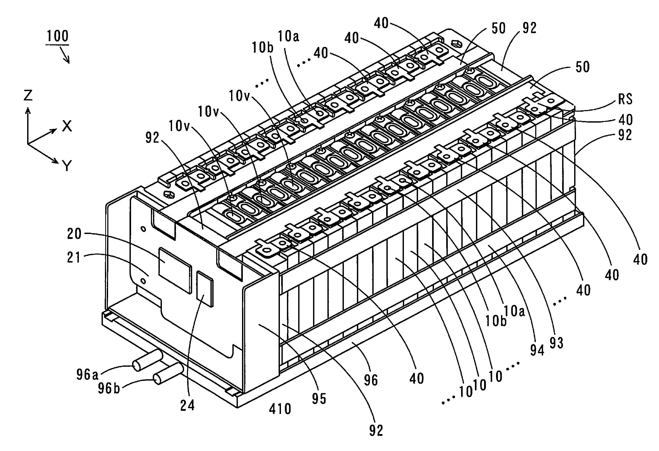
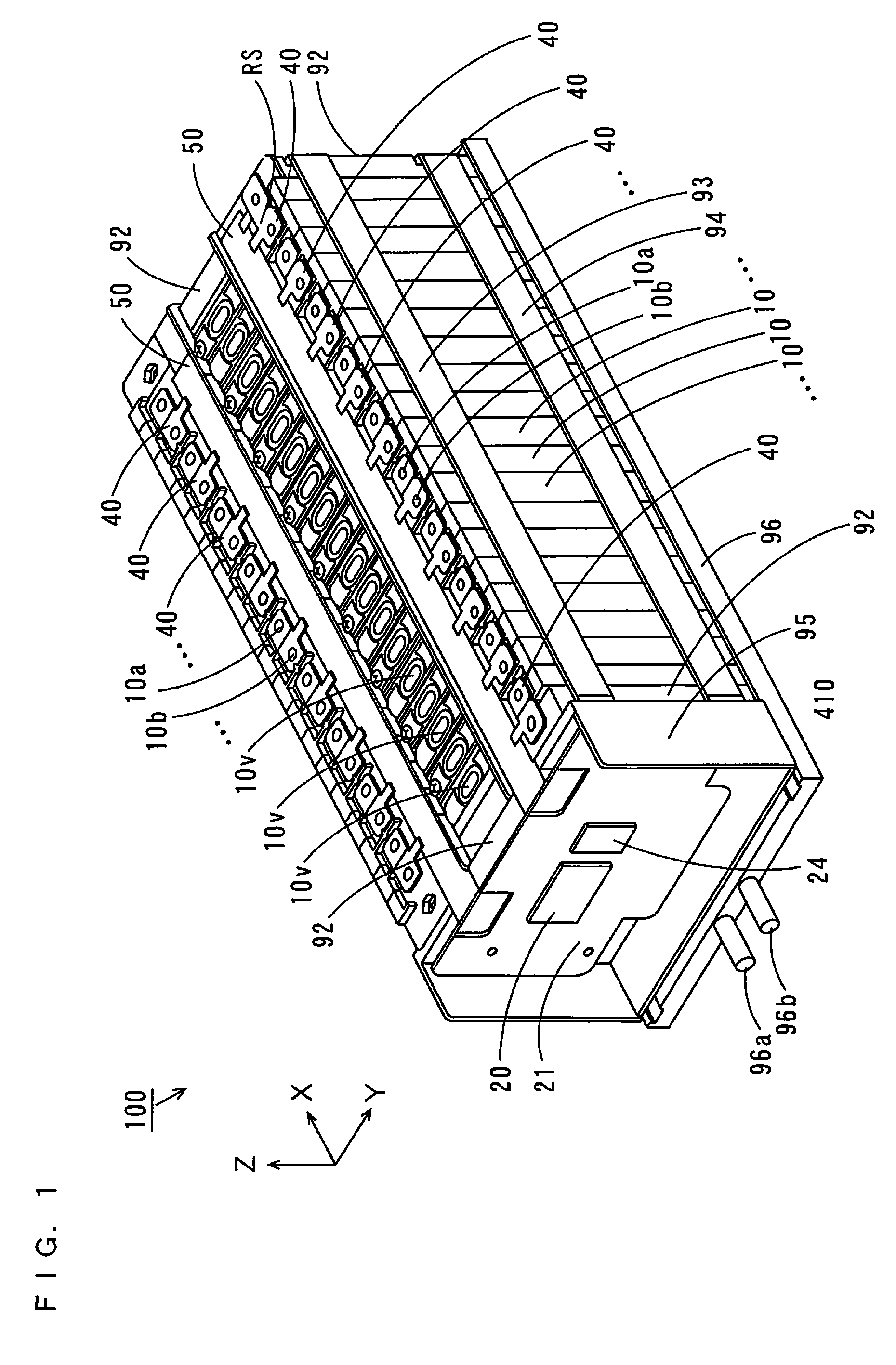
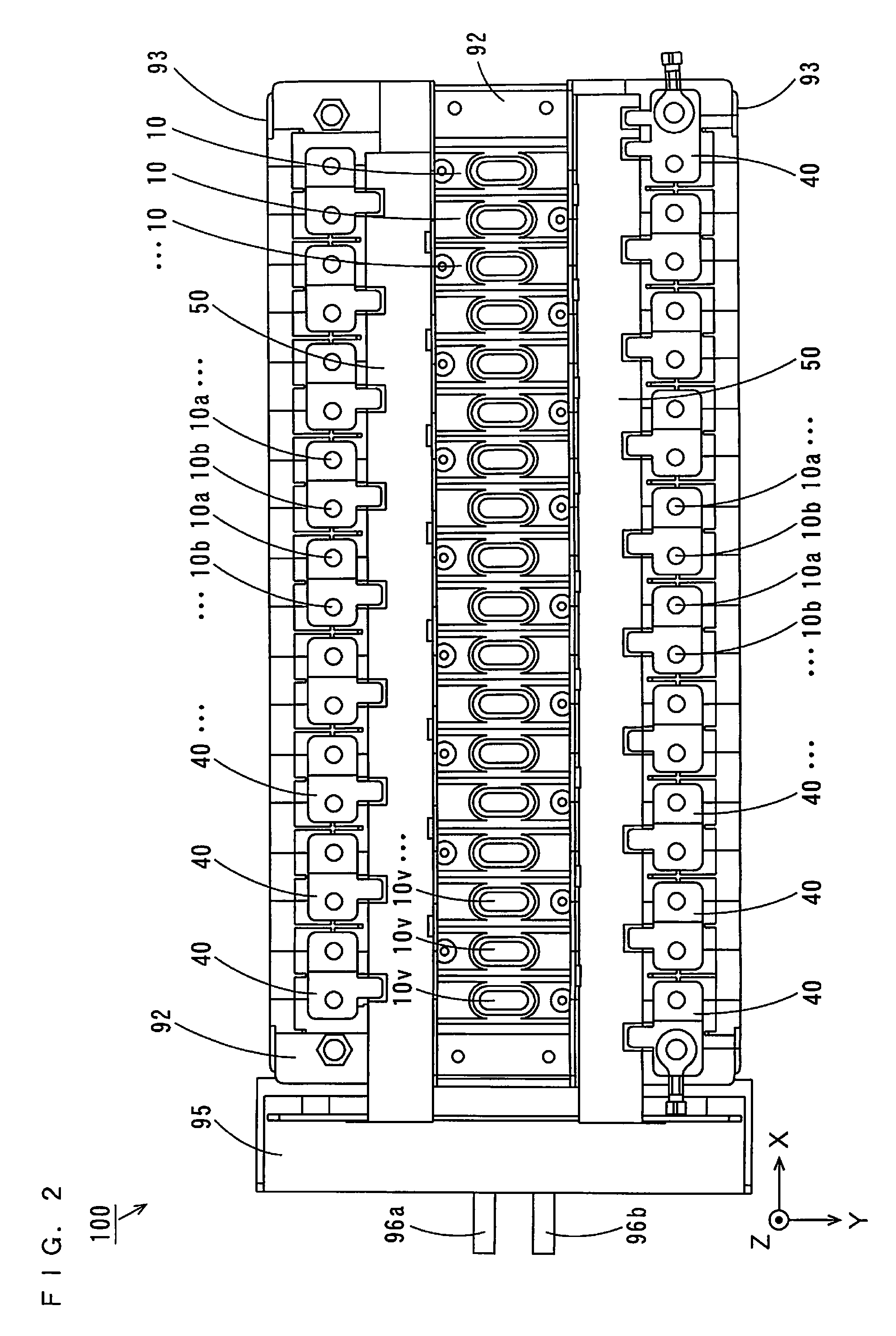
[0056]FIG. 1 is an external perspective view of a battery module 100 according to the present invention, and FIG. 2 is a plan view of the battery module 100 illustrated in FIG. 1. In FIGS. 1 and 2, and FIGS. 5 to 10, 12, 13, 15 and 17, described below, three directions that are perpendicular to one another are respectively defined as an X-direction, a Y-direction, and a Z-direction, as indicated by arrows X, Y and Z. In this example, the X-direction and the Y-direction are parallel to a horizontal plane, and the Z-direction is perpendicular to the horizontal plane.

[0057]As illustrated in FIGS. 1 and 2, in the battery module 100, a plurality of (18 in this example) battery cells 10 line up in the X-direction. The shape of the battery cell 10 is not particularly limited. The battery cell 10 may have a cross section of a trapezoid, a par...

second embodiment

(2) Second Embodiment

[0146]A battery system according to a second embodiment of the present invention will be described. The battery system according to the present embodiment includes the battery module 100 according to the above-mentioned first embodiment.

[0147](2-1) Overall Configuration

[0148]FIG. 18 is a schematic plan view illustrating a configuration of a battery system according to the second embodiment. As illustrated in FIG. 18, a battery system 500 includes battery modules 100a, 100b, 100c and 100d, a battery ECU 101, a contactor 102, a high voltage (HV) connector 520, and a service plug 530. The battery modules 100a to 100d have similar configurations to that of the battery module 100 according to the first embodiment. In this case, the separator S1 illustrated in FIG. 3 may be used. Alternatively, the separator S1 illustrated in FIG. 11 may be used. The separators S1 and S2 may be arranged in any one of the arrangement examples illustrated in FIGS. 5 to 10 and FIG. 12. T...

third embodiment

(3) Third Embodiment

[0171]An electric vehicle and a movable body according to a third embodiment of the present invention will be described. The electric vehicle includes a hybrid electric vehicle (HEV), a plug-in hybrid electric vehicle (PHEV), and a battery electric vehicle (EV). The electric vehicle and the movable body according to the present embodiment include the battery system 500 according to the second embodiment. An electric automobile will be described below as an example of the electric vehicle.

[0172](3-1) Configuration and Operation

[0173]FIG. 20 is a block diagram illustrating a configuration of the electric automobile according to the third embodiment. As illustrated in FIG. 20, an electric automobile 600 according to the present embodiment includes a vehicle body 610. The vehicle body 610 includes the above-mentioned battery system 500, a power converter 601, a motor 602, a drive wheel 603, an accelerator device 604, a brake device 605, a rotational speed sensor 606,...


PUM

PropertyMeasurementUnit
thermal conductionaaaaaaaaaa
thermalaaaaaaaaaa
electric poweraaaaaaaaaa

Abstract

A plurality of separators are arranged to line up in an X-direction on a cooling plate to respectively correspond to a plurality of battery cells. The separators corresponding to the odd-numbered battery cells and the separators corresponding to the even-numbered battery cells are arranged in opposite directions in the X-direction. On a bottom surface portion of each of the separators, the corresponding battery cell is arranged. In this case, one side surface or the other side surface of each of the battery cells contacts a side surface portion of the corresponding separator, and a bottom surface of each of the battery cells contacts the bottom surface portion of the corresponding separator.

Description

BACKGROUND OF THE INVENTION[0001](1) Field of the Invention[0002]The present invention relates to a battery module, and a battery system, an electric vehicle, a movable body, a power storage device, and a power supply device each including the battery module.[0003](2) Description of Related Art[0004]Battery modules including a plurality of chargeable / dischargeable battery cells are used for movable bodies such as electric automobiles or power supply devices storing electric power. In such battery modules, the battery cells are cooled to suppress rises in temperatures of the battery cells.[0005]For example, an automotive battery cooling system, which is discussed in JP 2008-159440 A, includes a plurality of battery cells, a side plate, and a cold plate. Each of the battery cells has a configuration in which a battery element is wrapped with an external film. The plurality of battery cells are respectively arranged so that a folded portion of the external film is grounded to an upper ...

Claims


Application Information

Patent Timeline
Patent Type & Authority Applications(United States)
IPC IPC(8): H01M10/50B60L11/18H02J7/00B60L3/00H01M10/44H01M10/60H01M10/613H01M10/625H01M10/647H01M10/6551H01M10/6555H01M10/6556H01M10/6567H01M50/209H01M50/503H01M50/507H01M50/522
CPCH01M2/1077H01M2/206H01M10/5004H01M10/5016H01M2220/20H01M10/5055H01M10/5057H01M10/5059H01M10/5032H01M10/625H01M10/647H01M10/6556H01M10/6557H01M10/6555H01M10/613Y02E60/10H01M50/503H01M50/507H01M50/209H01M50/522
Inventor OHKURA, KAZUMI
Owner SANYO ELECTRIC CO LTD
Why Eureka
Try Eureka