Shaft sealing ring for a barrier oil sealing system of a hydrogen-cooled generator

a technology of barrier oil and sealing system, which is applied in the direction of engine sealing, leakage prevention, machines/engines, etc., can solve the problems of longer service life of the shaft sealing ring, and achieve good emergency running properties

Inactive Publication Date: 2012-11-29
SIEMENS AG
View PDF9 Cites 4 Cited by
  • Summary
  • Abstract
  • Description
  • Claims
  • Application Information

AI Technical Summary

Benefits of technology

[0007]It is an object of the invention to provide a shaft sealing ring for a barrier oil sealing apparatus of a hydrogen-cooled generator, with the shaft sealing ring having good emergency running properties.

Problems solved by technology

This results in a longer service life of the shaft sealing ring.

Method used


Image

  • Shaft sealing ring for a barrier oil sealing system of a hydrogen-cooled generator
  • Shaft sealing ring for a barrier oil sealing system of a hydrogen-cooled generator
  • Shaft sealing ring for a barrier oil sealing system of a hydrogen-cooled generator

Examples


Embodiment Construction

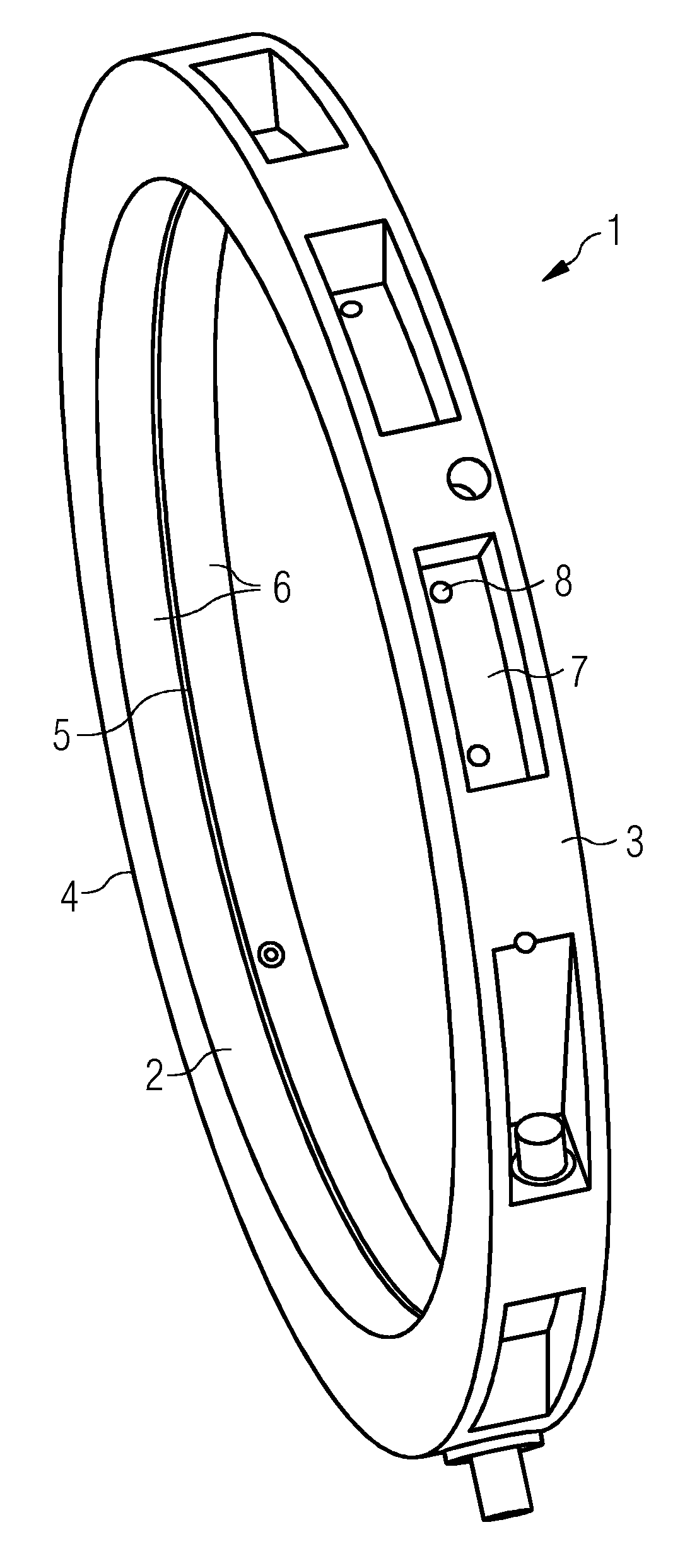
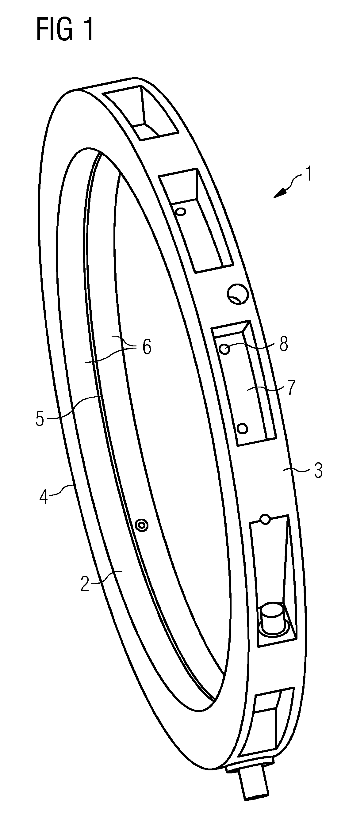
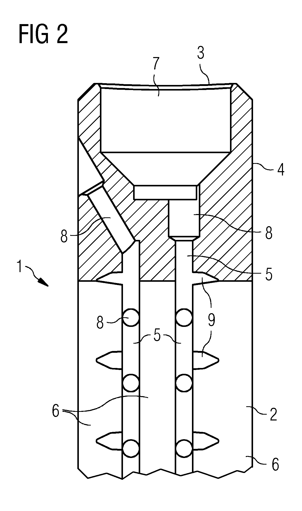
[0017]As can be seen in FIGS. 1 and 2, a shaft sealing ring 1 has an inner face 2, an outer face 3 and two end faces 4. The shaft sealing ring 1 is produced from a lead bronze material which comprises between 10% by mass and 20% by mass lead. A plurality of cutouts 7, in which oil inflow holes 8 are made, are provided in the outer face 3.

[0018]In the first embodiment, the shaft sealing ring 1 as shown in FIG. 1 has a circumferential furrow 5 provided in the inner face 2. Two running surface portions 6 extend from the circumferential furrow 5 as far as the outer edge of the shaft sealing ring 1. The oil inflow holes 8 extend from the cutouts into the circumferential furrow 5.

[0019]In contrast to the first embodiment, the second embodiment as shown inFIG. 2 has two circumferential furrows 5 in the inner face 2. As a result, three running surface portions 6 are formed, specifically two portions lying on the outside, which extend from the circumferential furrows 5 as far as the end face...


PUM


Abstract

A shaft sealing ring for a barrier oil sealing system of a hydrogen-cooled generator is designed, in the installed state, to bear radially against a generator shaft by way of its running surface arranged on the inner side and to interact with the generator shaft, under the action of a barrier oil, with hydrogen sealing, wherein the shaft sealing ring is produced from a lead bronze material.

Description

CROSS REFERENCE TO RELATED APPLICATIONS[0001]This application claims priority of European Patent Office application No. 11167707.6 EP filed May 26, 2011. All of the applications are incorporated by reference herein in their entirety.FIELD OF INVENTION[0002]A shaft sealing ring for a barrier oil sealing system of a hydrogen-cooled generator is provided, in the installed state, to bear radially against a generator shaft by way of its running surface arranged on the inner side and to interact with the generator shaft, under the action of a barrier oil, with hydrogen sealing, characterized in that the shaft sealing ring is produced from a lead bronze material.BACKGROUND OF INVENTION[0003]A rotating electrical machine, for example a motor or a generator, has a shaft for transmitting a torque. Heat released during operation of the electrical machine, in particular the heat released at the shaft, is dissipated by way of a cooling circuit. In this case, air, water or hydrogen is used in the...

Claims


Application Information

Patent Timeline
Patent Type & Authority Applications(United States)
IPC IPC(8): F16J15/40
CPCF16J15/443F16J15/40F16J15/441
Inventor CORDINER, CHRISTOPHERGUNTHER, THOMASLEHMANN, CHRISTOPHMAJCHRZAK, OLIVER
Owner SIEMENS AG
Why Eureka
Try Eureka