Input function display device
a display device and function technology, applied in the field of input function display devices, can solve the problems of increasing the thickness of the device, narrowing the display area, and deteriorating the display contrast by about 10%, so as to reduce the display quality and narrow the display area
- Summary
- Abstract
- Description
- Claims
- Application Information
AI Technical Summary
Benefits of technology
Problems solved by technology
Method used
Image
Examples
first embodiment
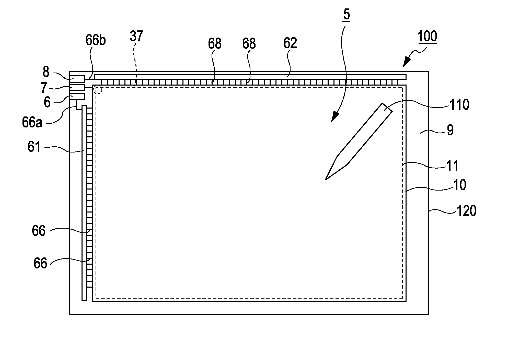
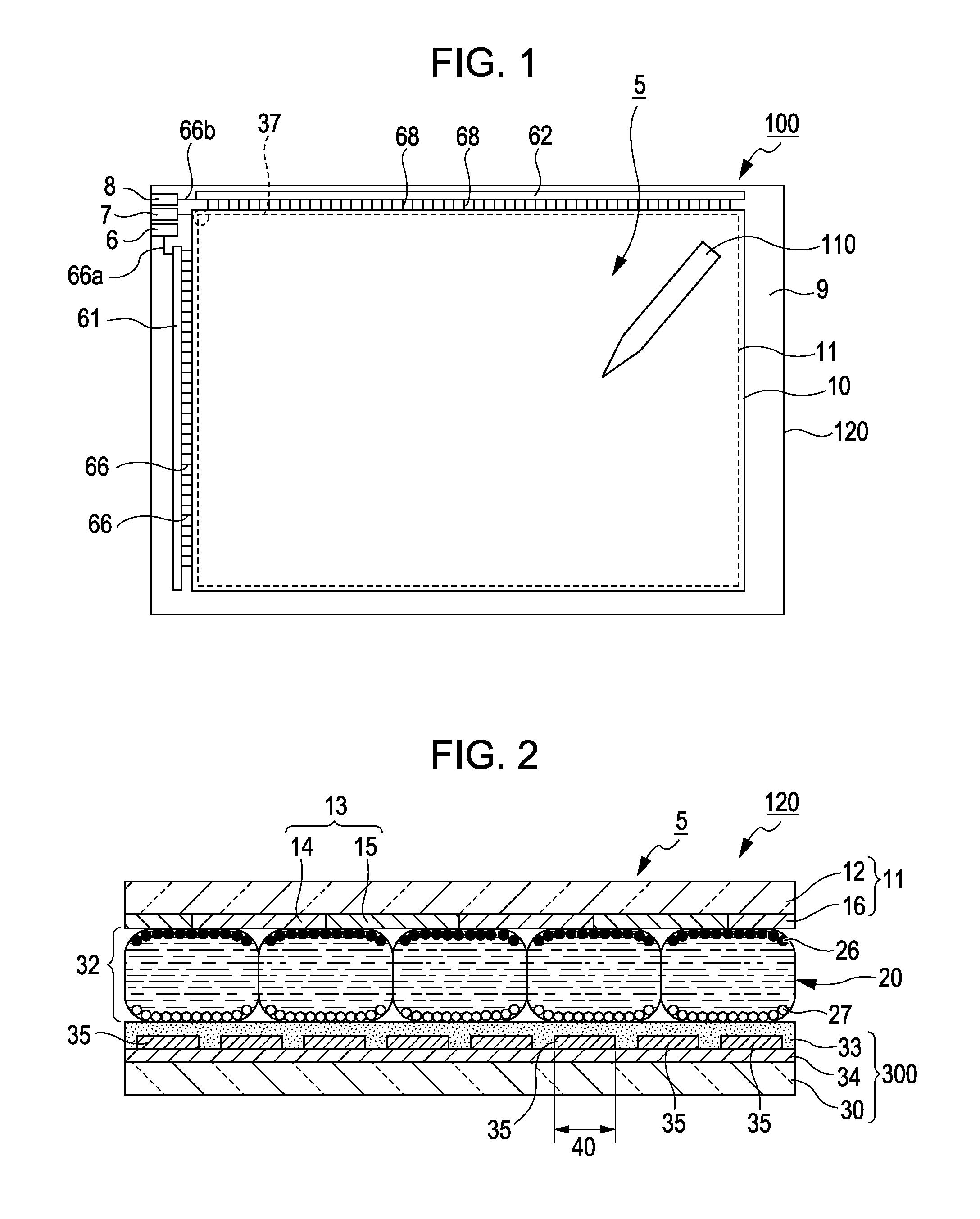
[0036]FIG. 1 is a plan view illustrating an overall configuration of an input function display device of the invention. FIG. 2 is a cross-sectional view illustrating a schematic configuration of a display body in the input function display device.
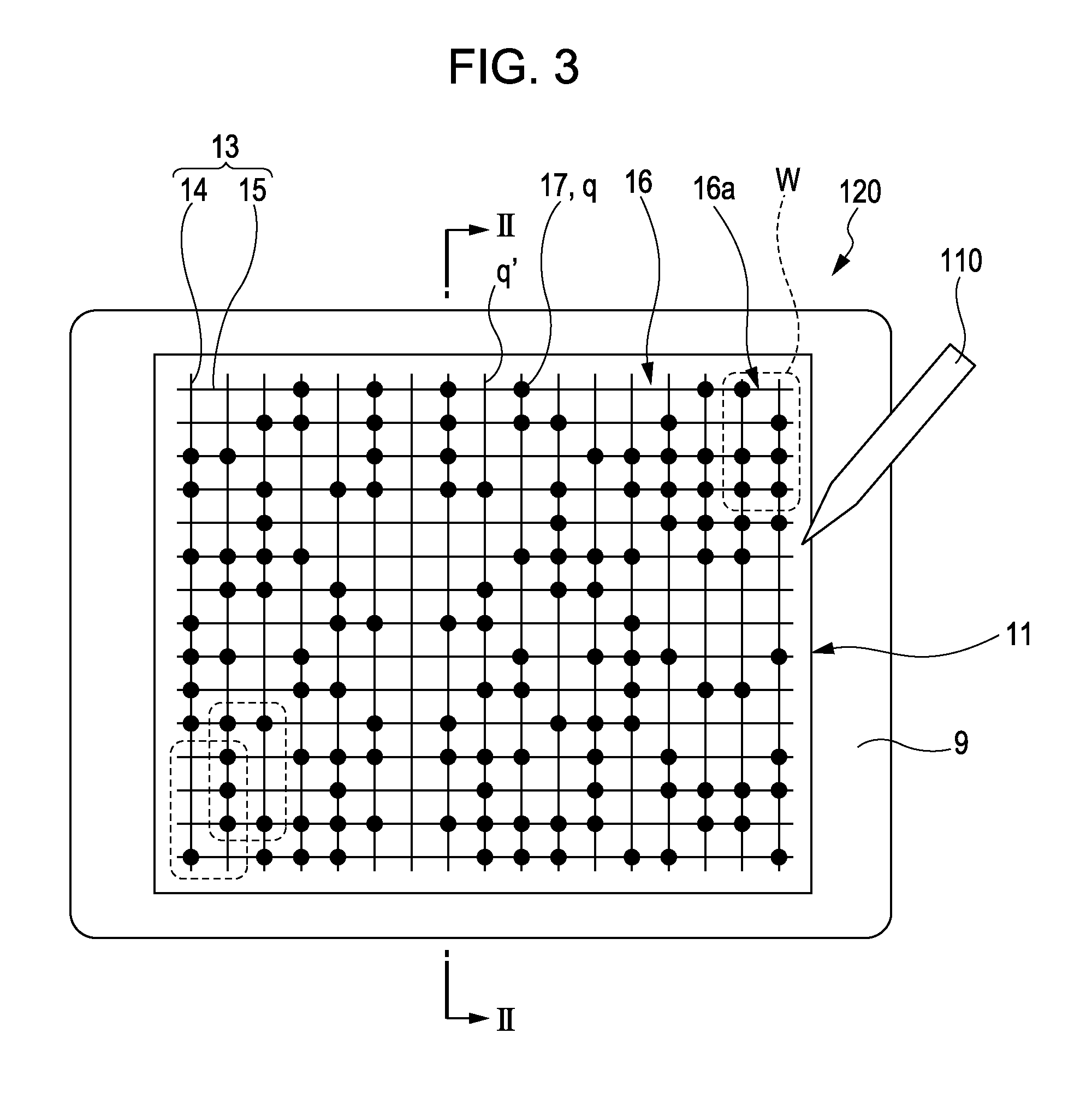
[0037]As shown in FIG. 1 and FIG. 2, the input function display device 100 includes an electronic pen (position information reading unit) 110, and a display body (display unit) 120, and is a display device which can perform handwriting input to a display face of the display body 120 using the electronic pen 110. Herein, handwriting information is displayed by acquiring time series data of a contact point of the electronic pen 110 to the display face of the display body 120 using the position information pattern 16 as a unit that detects position information (coordinate value in change of time) of the electronic pen 110 of the display body 120.
[0038]The display body 120 is formed of a display body (display portion) 10 having a coordinate bod...
example 1
[0074]FIG. 5A is diagram illustrating a position information pattern in Example 1, and FIG. 5B and FIG. 5C are diagrams illustrating a relationship between quadrants and marks at the reference position.
[0075]As shown in FIG. 5A, the position information pattern 19 is configured by the dots 18 assigned to the plurality of intersection points of the thin line patterns 14 and 15, represents a numerical value [0] at the intersection point where no dot 18 is provided, and represents numerical values [0] to [3] according to the number and the disposition of dots 18 at the intersection point areas, at the intersection points where the dots 18 are provided.
[0076]The position information pattern 19 has a reference position corresponding to the intersection point of the conductive pattern 13, and an arbitrary numerical value (coordinate value) is determined by the existence and nonexistence of the dots 18 or the disposition of the dot 18 with respect to the reference position. The shape of a ...
example 2
[0080]FIG. 6 is a diagram illustrating a position information pattern in Example 2.
[0081]As shown in FIG. 6, the position information pattern 23 in the example has a conductive pattern 130 in which a thin line pattern (first thin line pattern) 140 with one set of three thin lines 14a, 14b, and 14c and a thin line pattern 150 with one set of three thin lines 15a, 15b, and 15c (second thin line pattern) are arranged in a lattice shape, and it is possible to identify a rotation state of the conductive pattern 130 by asymmetry between pitch widths of the thin lines 14a, 14b, and 14c and pitch widths of the thin lines 15a, 15b, and 15c.
[0082]The reference position of the position information pattern 23 is regulated by the intersection point of the thin lines 14b and 15b of the thin line patterns 140 and 150 intersecting with each other, and the coordinate value is represented by the disposition of the dots 18 with respect to the reference position.
[0083]The coordinate value is encoded b...
PUM
 Abstract
Description
Claims
Application Information
 - R&D
- Intellectual Property
- Life Sciences
- Materials
- Tech Scout
- Unparalleled Data Quality
- Higher Quality Content
- 60% Fewer Hallucinations
Browse by: Latest US Patents, China's latest patents, Technical Efficacy Thesaurus, Application Domain, Technology Topic, Popular Technical Reports.
© 2025 PatSnap. All rights reserved.Legal|Privacy policy|Modern Slavery Act Transparency Statement|Sitemap|About US| Contact US: help@patsnap.com


