Seal structure of mechanical device and wind turbine generator

a mechanical device and wind turbine technology, applied in the direction of liquid fuel engines, vessel construction, marine propulsion, etc., can solve the problems of lubricant oil leakage, insufficient supply of lubricant oil for required parts, and inability to supply lubricant oil to sufficient quantities, so as to improve the maintenance and repair effect of the seal structure, easy placement, and easy alignmen

Inactive Publication Date: 2012-11-29
MITSUBISHI HEAVY IND LTD
View PDF5 Cites 4 Cited by
  • Summary
  • Abstract
  • Description
  • Claims
  • Application Information

AI Technical Summary

Benefits of technology

[0020]According to the present invention, the maintainability of the seal structure is improved in the reason where the rotation shaft is inserted in the housing. Further, it is possible to obtain the seal structure of the mechanical device and the wind turbine generator, in particular, in which the seal structure can be arranged smoothly and freely-replaceable in a small space disposed between the shrink disk tightening and connecting the main shaft and the input shaf

Problems solved by technology

In the bath lubrication system, there is uncertainty in supply of the lubricant oil and a chance that the required parts are not supplied with sufficient amount of the lubricant oil.
In the forced lubrication system, leaking of the lubricant oil where the rotation shaft is inserted in the housing, may cause an issue.
The lubricant oil is forced into the bearing at high pressure and thus, the lub

Method used


Image

  • Seal structure of mechanical device and wind turbine generator
  • Seal structure of mechanical device and wind turbine generator
  • Seal structure of mechanical device and wind turbine generator

Examples


Embodiment Construction

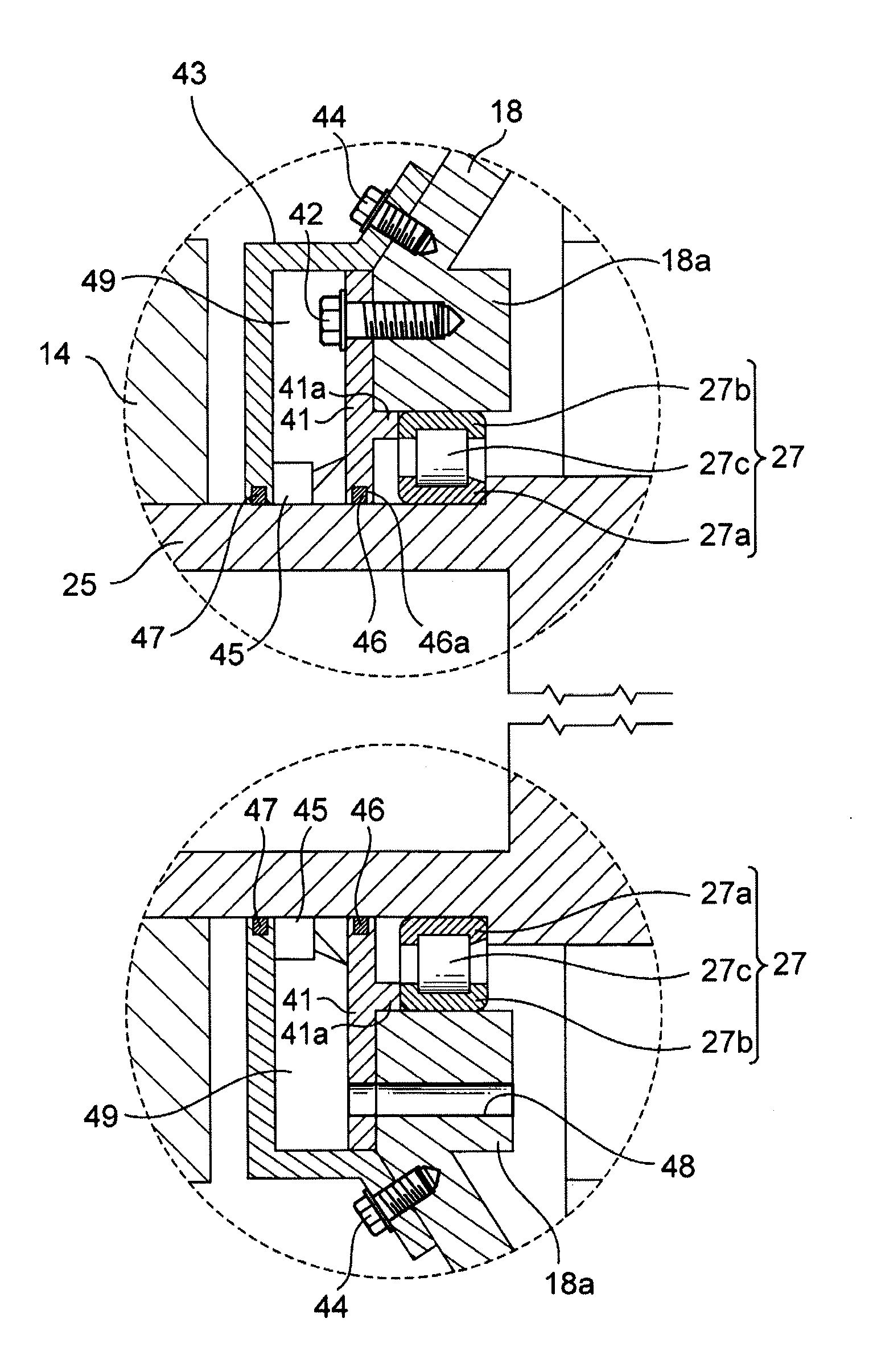
[0029]An embodiment of the present invention will now be described in detail with reference to the accompanying drawings. Herein, an exemplary case where the present invention is applied to a step-up gear of a wind turbine generator. However, this is not limitative and the present invention can be applied, in general, to a variety of mechanical devices having a rotation shaft in a housing.

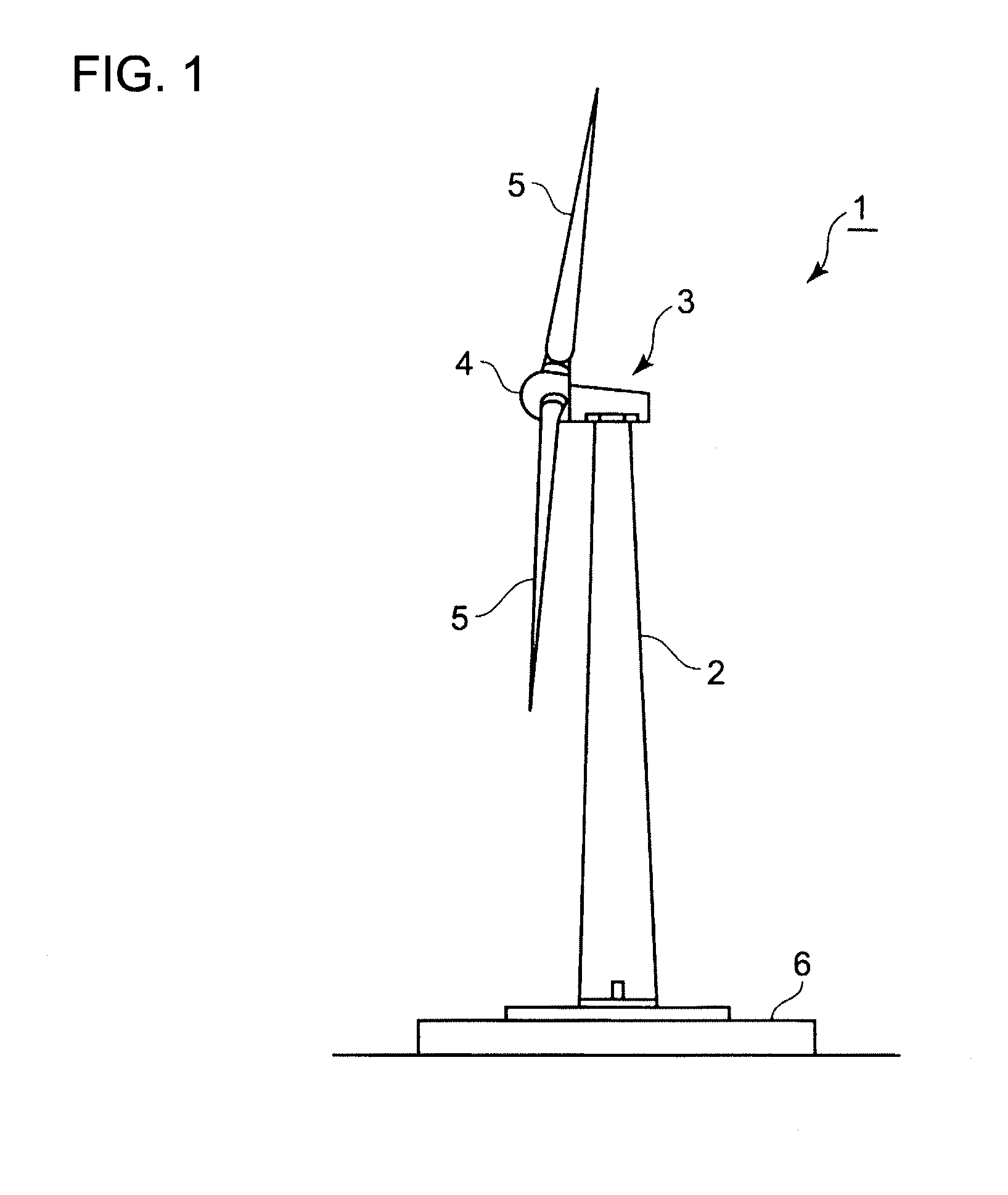
[0030]FIG. 1 is a side view of a wind turbine generator 1 in relation to an embodiment of the present invention showing a structure thereof. The wind turbine generator 1 includes a tower 2 installed upright on a base 6, a nacelle installed atop the tower 2, a rotor heat mounted rotatably to the nacelle 3 and a blade 5 mounted to the rotor head 4. The rotor head 4 and the blade 5 constitute a wind turbine rotor.

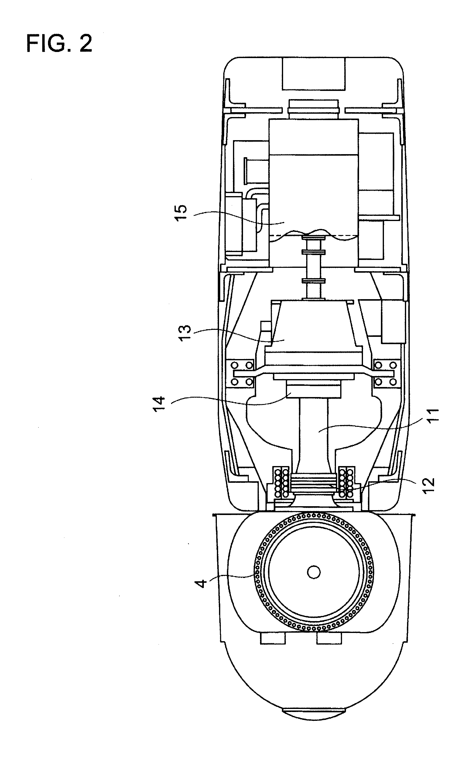
[0031]As shown in FIG. 2, an end of a main shaft 11 is coupled to the rotor head 4 and the main shaft 11 is supported rotatably by a main shaft bearing 12. Other end of the main shaft 11 is c...


PUM


Abstract

It is intended to improve maintainability of a seal structure in a place where the rotation shaft is inserted in the housing. A seal structure of a mechanical device is provided with a housing 18 having an opening in which an input shaft 21 is inserted, a holding plate 41 which is connected to a periphery of the opening of the housing 18 and which has an opening in which the input shaft 21 is inserted, a felt ring 46 which is provided in the holding plate 41 and which seals a space between the holding plate 41 and the input shaft 21, a separable housing 43 which is provided to cover the holding plate 41 and a separable oil seal 45 which seals the space between the holding plate 41 and the input shaft 21 and a space between the cover and the rotation shaft. The holding plate 41 has an arc-shaped projection 47b extending to a position where the projection comes in contact with a wall surface of the separable housing 43 and a housing space for housing the oil seal 45 is formed by the wall surface of the cover, the inner periphery of the arc-shaped projection 47b and the wall surface of the holding plate 41.

Description

TECHNICAL FIELD[0001]The present invention relates to a seal structure of a mechanical device, and in particular to a seal structure which prevents leaking of lubricant oil where a rotation shaft is inserted in a housing.BACKGROUND ART [0002]It is necessary to supply lubricant oil to all parts in order for a mechanical device such as a step-up gear and a reduction gear to function. The mechanical device is constituted of gears and other mechanical components. A bath lubrication system is the most commonly used system for supplying the lubricant oil to the required parts of the mechanical device. In the bath lubrication system, the lubricant oil adheres to the gear by dipping at least a part of the gear in a bath of the lubricant oil or the lubricant oil adhered to the gear splashes so as to supply the lubricant oil to the required parts such as a gear surface and a bearing.[0003]In the bath lubrication system, there is uncertainty in supply of the lubricant oil and a chance that the...

Claims


Application Information

Patent Timeline
IPC IPC(8): F03D11/00F16N7/38F16J15/16
CPCF03D11/0008F03D11/02F05B2240/57Y02E10/722F16H57/08F16J15/3456F05B2260/4031F03D80/70F03D15/00Y02E10/72F05B2260/98F03D15/10
Inventor TAKEUCHI, HIROAKIHOTTA, KAZUROOKADA, KOZUENISHIDA, HIDEAKI
Owner MITSUBISHI HEAVY IND LTD
Why Eureka
Try Eureka