
Liquid-crystal display device

a liquid crystal display and display device technology, applied in the field of liquid crystal display devices, can solve the problems of affecting the display quality, so as to prevent light leakage

Inactive Publication Date: 2012-12-06
SHARP KK
View PDF2 Cites 37 Cited by
  • Summary
  • Abstract
  • Description
  • Claims
  • Application Information

AI Technical Summary

Benefits of technology

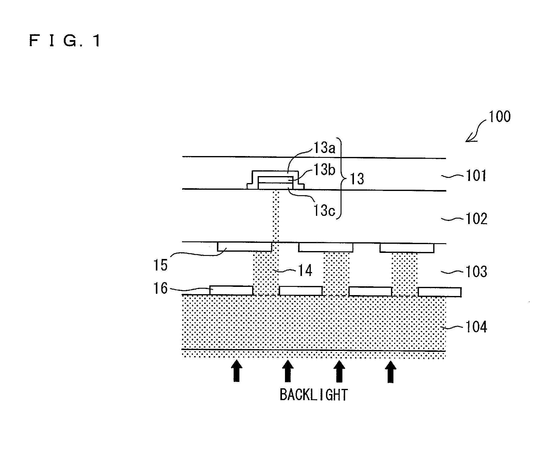
[0025]According to the arrangement, the light blocking member is provided on the touch panel so that a part of the light blocking member and a part of the at least one black matrix overlap each other when the light blocking member is seen from the touch panel side. This makes it possible to block light which enters the color filter substrate and then leaks from a vicinity of the at least one black matrix toward the touch panel without being blocked by at least one the black matrix.
[0028]Therefore, even light which leaks from a vicinity of the at least one black matrix is blocked by the touch panel. This yields an effect of preventing light leakage from the touch panel.

Problems solved by technology

However, if defects such as a pinhole and lack of a pattern occur in the second black matrix, a leakage of light from a backlight occurs in a part in which such defects occur.
This may cause a deterioration in display quality.
This causes an abnormality in alignment of liquid crystal in vicinities of the respective protrusions.
This causes light to be unexpectedly transmitted through a region in which such an alignment abnormality as described above occurs.
Particularly, the light leakage causes a dramatic deterioration in display quality in a case where a bright text and / or a graphic is displayed in a dark display surface.

Method used


Image

  • Liquid-crystal display device
  • Liquid-crystal display device
  • Liquid-crystal display device

Examples


embodiment 1

[0059]One embodiment of the present invention is described below with reference to FIG. 1 to FIG. 3.

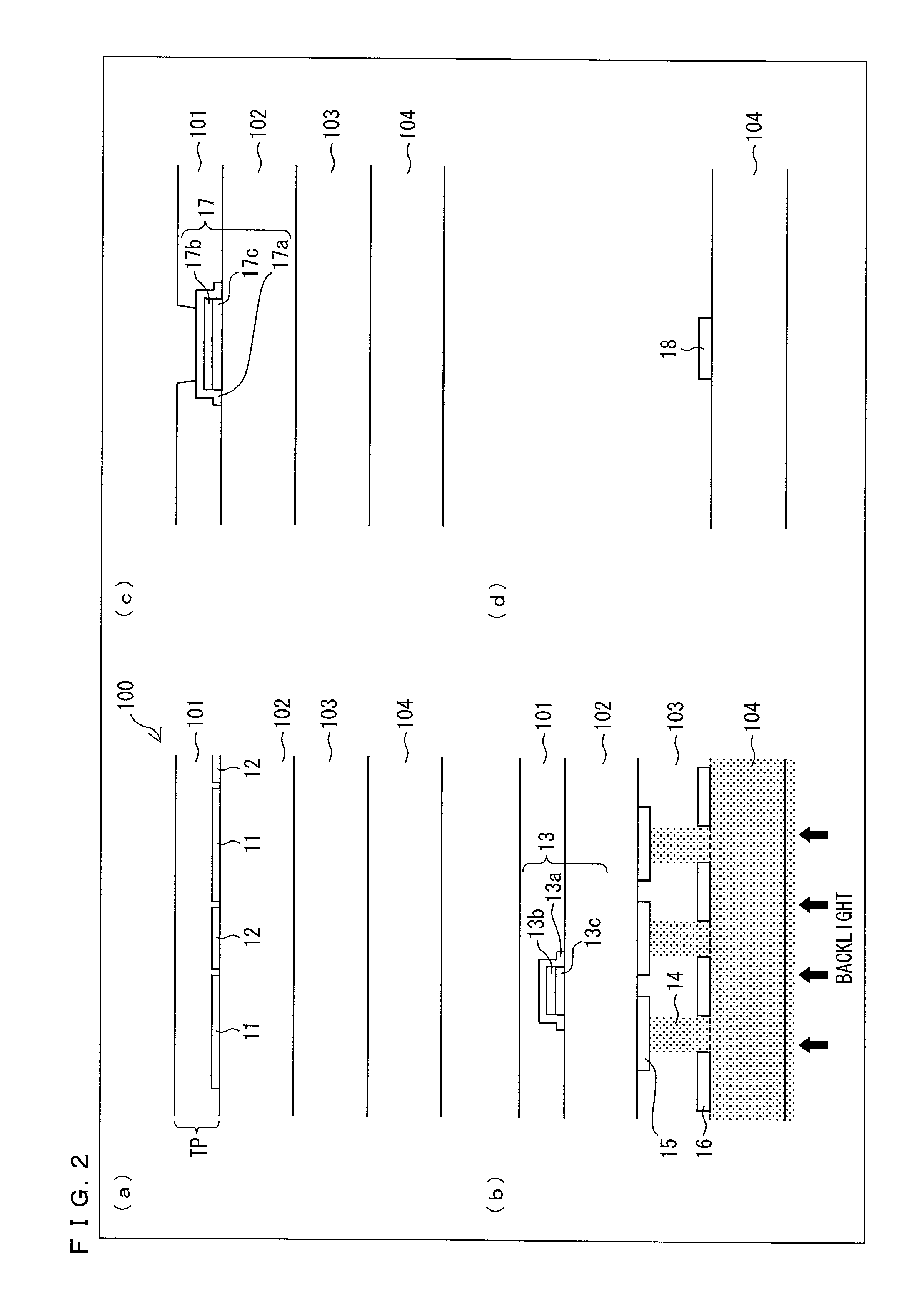
[0060](a) of FIG. 2 is a cross-sectional view of a panel pixel section of a liquid crystal display device 100. (b) of FIG. 2 is a cross-sectional view of a panel peripheral part of the liquid crystal display device 100. The liquid crystal display device 100 includes a touch panel 101, a color filter substrate 102, a liquid crystal layer 103, and a back substrate 104 (see (a) and (b) of FIG. 2).

[0061]The touch panel 101 is a capacitive touch panel integrated with the liquid crystal display device 100 (in-cell touch panel incorporated in the liquid crystal display device 100). According to the present embodiment, the touch panel 101 has only one layer. Alternatively, the touch panel 101 may have a plurality of layers.

[0062]The touch panel 101 includes touch electrodes 11 and floating electrodes 12 in the panel pixel section (see (a) of FIG. 2).

[0063]The touch electrodes 11 are terminals...

embodiment 2

[0079]A second embodiment of the present invention is described below with reference to FIG. 4 to FIG. 6. Note that a description of members which are identical to those described in Embodiment 1 is to be omitted. The present embodiment discusses an arrangement for preventing light leakage from occurring in the panel pixel section.

[0080](a) of FIG. 4 is a sectional view of a panel pixel section of a liquid crystal display device 200. The liquid crystal display device 200 includes a touch panel 201, a color filter substrate 202, a liquid crystal layer 203, and a back substrate 204 (see (a) of FIG. 4).

[0081]The touch panel 201 is a capacitive touch panel integrated with the liquid crystal display device 200 (in-cell touch panel incorporated in the liquid crystal display device 200) (see (a) of FIG. 4). According to the present embodiment, the touch panel 201 has only one layer. Alternatively, the touch panel 201 may have a plurality of layers.

[0082]The touch panel 201 includes touch e...

embodiment 3

[0104]A third embodiment of the present invention is described below with reference to FIG. 7 to FIG. 10.

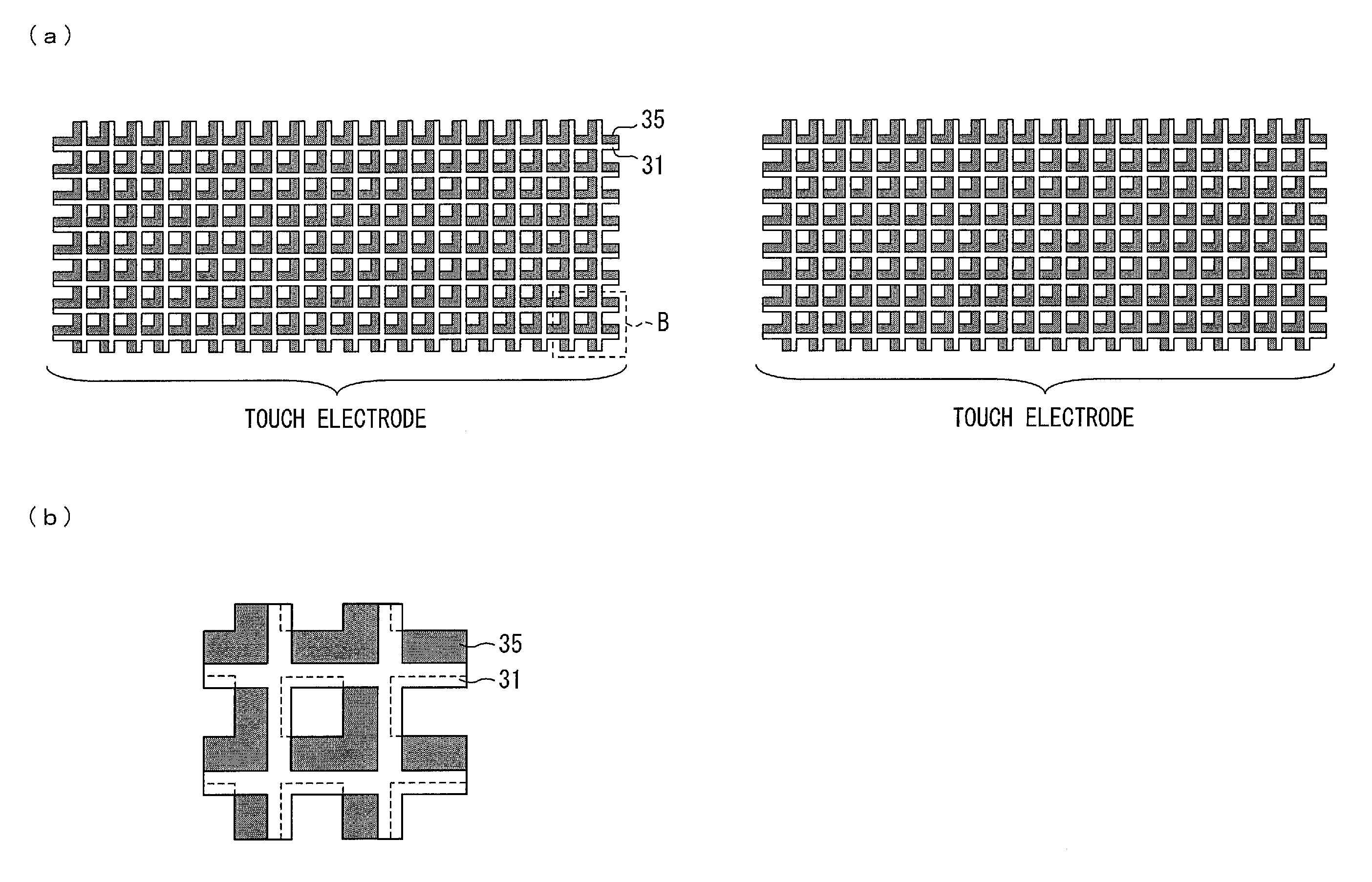
[0105]The present embodiment is arranged to cause touch electrodes 31 provided in a grid pattern prevent to prevent light leakage.

[0106](a) of FIG. 7 is a cross-sectional view of a panel pixel section of a liquid crystal display device 300. The liquid crystal display device 300 includes a touch panel 301, a color filter substrate 302, a liquid crystal layer 303, and a back substrate 304 (see (a) of FIG. 7).

[0107]The touch panel 301 is a capacitive touch panel integrated with the liquid crystal display device 300 (in-cell touch panel incorporated in the liquid crystal display device 300) (see (a) of FIG. 7). According to the present embodiment, the touch panel 301 has only one layer. Alternatively, the touch panel 301 may have a plurality of layers.

[0108]The touch panel 301 includes touch electrodes 31 and floating electrodes 32 in the panel pixel section.

[0109]According to the co...


PUM


Abstract

A liquid crystal display device (100) includes: a touch panel (101); and a color filter substrate (102) having (i) a first surface which faces the touch panel (101) and (ii) a second surface which is opposite from the first surface and on which at least one black matrix (15) is provided, the touch panel (101) including an Al layer (13c) that has a light blocking property, and in order to block light which enters the color filter substrate (102) from the second surface side and then leaks from a vicinity of the at least one black matrix (15) toward the touch panel (101), the Al layer (13c) being provided on the touch panel (101) so that a part of the Al layer (13c) and a part of the at least one black matrix (15) overlap each other when the Al layer (13c) is seen from the touch panel (101) side.

Description

TECHNICAL FIELD[0001]The present invention relates to a liquid crystal display device which is provided with a touch panel function.BACKGROUND ART[0002]In recent years, a sophisticated liquid crystal display device has been provided in which convenience for a user has been enhanced by providing a liquid crystal display panel with a touch panel function as a function other than an information display function.[0003]Specifically, a liquid crystal display device has been provided which includes a liquid crystal display panel and a touch panel. The liquid crystal display panel serves as a display section that displays information including a text and an image. The touch panel is provided on the display surface side of the liquid crystal display panel or on an opposite side from the display surface side.[0004]Further, it is highly possible that a high-value added liquid crystal display device will be produced in which a liquid crystal display panel is provided with an in-cell capacitive ...

Claims


Application Information

Patent Timeline
IPC IPC(8): G09G3/36G06F3/041
CPCG02F1/13338G06F3/0412G02F1/1336G02F1/133512G06F2203/04107G06F3/0443
Inventor MISAKI, KATSUNORI
Owner SHARP KK
Learn More