Mobile communication system

a communication system and mobile technology, applied in the field of mobile communication systems, can solve problems such as system performance degradation, and achieve the effects of reducing the load of user equipment devices, simplifying search operations, and reducing the self-interference of relay devices

Active Publication Date: 2012-12-06
MITSUBISHI ELECTRIC CORP
View PDF6 Cites 26 Cited by
  • Summary
  • Abstract
  • Description
  • Claims
  • Application Information

AI Technical Summary

Benefits of technology

[0067]According to the mobile communication system of the present invention, the relay device performs radio communication with the user equipment device using the carrier having a different frequency from that of the carrier used in radio communication with the base station device, whereby it is possible to reduce the self-interference of the relay device, that is, the interference of the radio communication between the relay device and the base station device and the radio communication between the relay device and the user equipment device. In addition, the base station device performs radio communication with the user equipment device using the carrier having the same frequency as that of the carrier used in the radio between the relay device and the user equipment device, whereby it is possible to simplify the search operation in which the user equipment device searches for the base station device or relay device as a communication target. This reduces the load of the user equipment device in a search operation. Therefore, it is possible to prevent the interference in the mobile communication system and reduce the load of the user equipment device in the search operation.
[0068]Further, according to the mobile communication system of the present invention, the relay device performs radio communication with the user equipment device using the carrier having a different frequency from that of the carrier used in radio communication with the base station device, whereby it is possible to reduce the self-interference of the relay device, that is, the interference of the radio communication between the relay device and the base station device and the radio communication between the relay device and the user equipment device. In addition, the base station device notifies the user equipment device of the information related to the radio communication link between the relay device and the user equipment device, whereby the user equipment device is allowed to search for the relay device based on the

Problems solved by technology

The time division multiplexing described above decreases the thro

Method used


Image

  • Mobile communication system
  • Mobile communication system
  • Mobile communication system

Examples


first embodiment

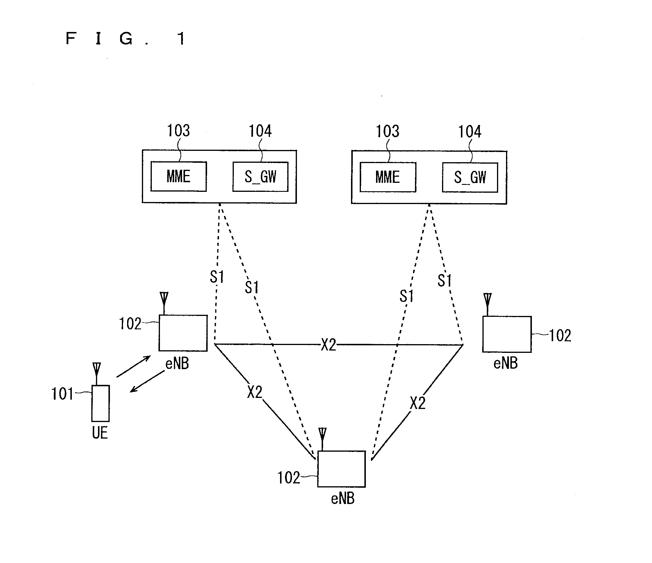
[0095]FIG. 7 is a block diagram showing an overall configuration of an LTE mobile communication system, which is currently under discussion of 3GPP. Currently, 3GPP is studying an overall system configuration including closed subscriber group (CSG) cells (Home-eNodeBs (Home-eNB; HeNB) of E-UTRAN, Home-NB (HNB) of UTRAN) and non-CSG cells (eNodeB (eNB) of E-UTRAN, NodeB (NB) of UTRAN, and BSS of GERAN) and, as to E-UTRAN, is proposing the configuration as shown in FIG. 7 (see Chapter 4.6.1 of Non-Patent Document 1).

[0096]FIG. 7 is described. A user equipment device (hereinafter, referred to as “user equipment” or “UE”) 71 is capable of performing radio communication with a base station device (hereinafter, referred to as “base station”) 72 and transmits / receives signals through radio communication. The base stations 72 are classified into an eNB 72-1 and a Home-eNB 72-2. The eNB 72-1 is connected to an MME / S-GW unit (hereinafter, referred to as an “MME unit”) 73 including an MME, S-G...

first modification

of First Embodiment

[0179]A first modification of the first embodiment is described. In the first embodiment described above, the same frequency band or the like is used in the uplink (direct link) from a user equipment being served by a donor cell and the uplink (access link) from a user equipment being served by a relay node, and accordingly, uplink interference occurs in the coverage of the donor cell at times. Uplink scheduling is performed by the serving cell. That is, the donor cell and relay node individually perform uplink scheduling on user equipments being served thereby. Accordingly, for reducing the uplink interference through uplink scheduling, a control delay increases and a mobile communication system is complicated as well.

[0180]The uplink interference is described with reference to FIG. 19. FIG. 19 is a location diagram for illustrating the uplink interference. The portions of FIG. 19 corresponding to those of FIG. 15 are denoted by the same reference numerals, which...

second embodiment

[0213]A second embodiment of the present invention discloses a solution different from that of the first embodiment for the problem of the present invention. The solution in the second embodiment is disclosed below. The donor cell notifies a user equipment being served thereby of the information of the access link used in a relay node being served thereby. The user equipment that has received the information performs a search operation using the carrier used in the access link.

[0214]Alternatively, the relay node may notify a user equipment being served thereby of the information of the direct link used in the donor cell. The user equipment that has received the information performs a search operation using the carrier used in the direct link.

[0215]As a result, the user equipment can ascertain the carrier frequency that is used in the access link by the relay node. Therefore, it is possible to reduce the load of a user equipment in a search operation.

[0216]Specific examples of the in...


PUM


Abstract

A mobile communication system capable of preventing interference in a communication system as well as reducing the load of a user equipment in a search operation. In the mobile communication system, radio communication is performed using a carrier having the same frequency in a direct link between a donor cell and a user equipment being served thereby and an access link between a relay node and a user equipment being served thereby. In a backhaul link between the donor cell and the relay node, radio communication is performed using a carrier having a different frequency from that of the carrier used in the direct link and the access link.

Description

TECHNICAL FIELD [0001]The present invention relates to a mobile communication system in which a base station performs radio communication with a plurality of user equipments.BACKGROUND ART [0002]Commercial service of a wideband code division multiple access (W-CDMA) system among so-called third-generation communication systems has been offered in Japan since 2001. In addition, high speed down link packet access (HSDPA) service for achieving higher-speed data transmission using a downlink has been offered by adding a channel for packet transmission (high speed-downlink shared channel (HS-DSCH)) to the downlink (dedicated data channel, dedicated control channel). Further, in order to increase the speed of data transmission in an uplink direction, service of a high speed up link packet access (HSUPA) system has been offered. W-CDMA is a communication system defined by the 3rd generation partnership project (3GPP) that is the standard organization regarding the mobile communication syst...

Claims


Application Information

Patent Timeline
IPC IPC(8): H04W72/04H04B7/14
CPCH04L5/001H04L5/0062H04W88/04H04W28/04H04W28/06H04L5/0073H04W84/047H04B7/15507H04L5/0053
Inventor MAEDA, MIHOMOCHIZUKI, MITSURUIWANE, YASUSHIKAKEHI, YUJINAKAZAWA, MASAYUKISUEMITSU, TAISEI
Owner MITSUBISHI ELECTRIC CORP
Why Eureka
Try Eureka