

Clock recovery method and clock recovery arrangement for coherent polarization multiplex receivers
a clock recovery and receiver technology, applied in the field of polarisation multiplex systems with coherent receivers, can solve problems such as phase error values controlling the pll
- Summary
- Abstract
- Description
- Claims
- Application Information
AI Technical Summary
Benefits of technology
Problems solved by technology
Method used
Image

Examples
Embodiment Construction
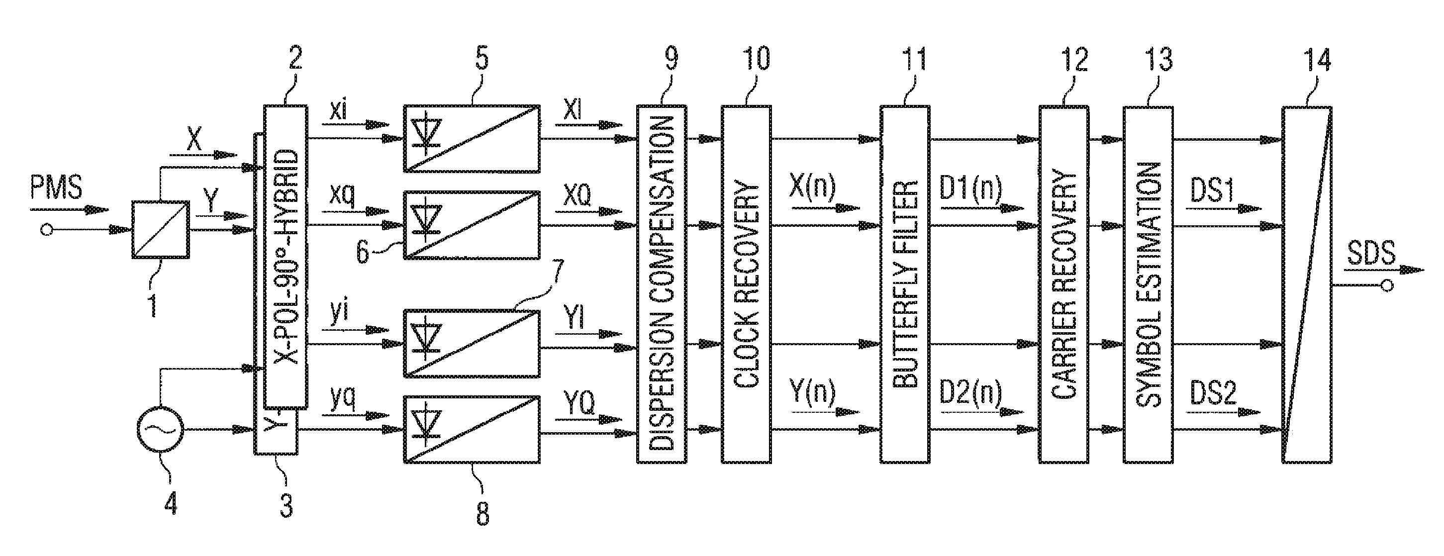
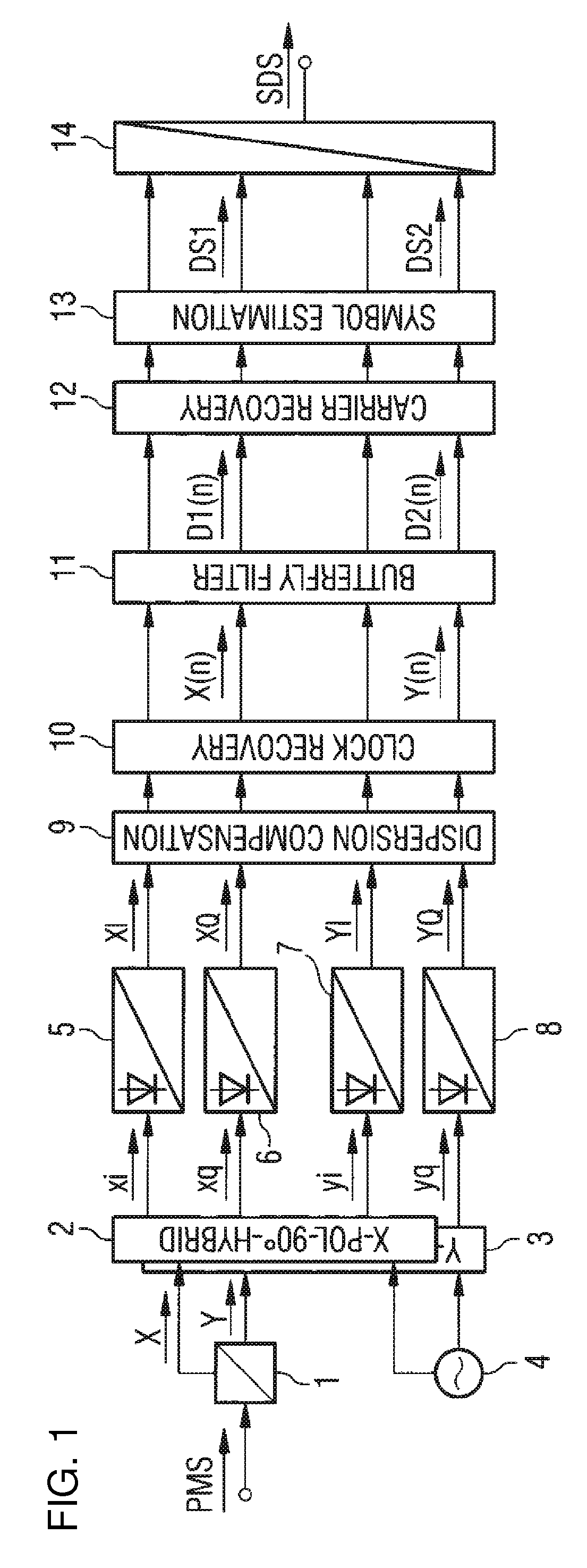
[0047]FIG. 3 shows a simplified diagram of a presently preferred clock recovery arrangement according to the invention. The analogue signal components xi, xq and yi, yq output by the 90°-hybrids (FIG. 1) are fed to analogue-digital converters 20, 21 of a first sample unit 15 and 24, 25 of a second sample unit 16.
[0048]Sequences of the sampled component values XI, XQ and YI, YQ, (time variable [n] is here usually omitted) representing the signal components xi, xq, yi, yq, are fed to a combined phase error detector unit 17 to determine resulting phase error values XWPE, XRPE which are fed via a loop filter 18 as control signal CS—where required after digital-analogue conversion—to a controlled oscillator 19 (CO; numerical controlled or in the analogue domain voltage controlled) of a phase locked loop (PLL). The controlled oscillator 19 supplies the sampling units 15, 16 with a common clock signal CL or with separate clock signals. The clock signals may be adapted e.g. to different int...
PUM
 Abstract
Description
Claims
Application Information