Battery assembly

a battery and assembly technology, applied in the direction of secondary cell servicing/maintenance, cell structural combination, cell components, etc., can solve the problems of difficult to properly hold the cells in place, difficult to manufacture, and high electrical losses, so as to reduce electrical losses, reduce electrical losses, and reduce electrical losses.

Inactive Publication Date: 2012-12-06
ALELION ENERGY SYST AB
View PDF0 Cites 27 Cited by
  • Summary
  • Abstract
  • Description
  • Claims
  • Application Information

AI Technical Summary

Benefits of technology

[0010]Thus, in the inventive design the first metal plate functions both as a supporting means for holding the cell block in place as well as a rather massive electrical conductor. This conductor is in turn capable of, on the one hand, leading an electrical current with small electrical losses to and from the first electrode terminals of the cells in the block and, on the other hand, leading an electrical current directly to and from the electronic circuit provided on the PCB without having to conduct (or providing means for conducting) the current through additional components, such as cables and cable contacts, for connecting the plate and the PCB.
[0011]An advantageous effect achieved with this design is a reduction of the electrical losses due to the large conductor (compared to e.g. the conventional Ni-strips) and the direct electrical connection between the metal plate and the PCB. Another advantageous effect of this design is that it makes the manufacture more efficient since cables are not required. A further advantageous effect is the dual function (supporting-conducting) of the metal plate which, for instance, leads to a reduction in the number of components and thereby makes the manufacture more cost-effective.

Problems solved by technology

This leads to somewhat different challenges, for instance how the heat developed during use should be handled and how the pack should be physically designed for holding the cells and the associated electronics together.
Although this traditional design is well established and generally applied it has some drawbacks in that the method of production is rather complicated and time-consuming, in that it is sometimes difficult to hold the cells in place properly using only the Ni-strip, and in that the electrical losses are relatively high.

Method used


Image

  • Battery assembly
  • Battery assembly
  • Battery assembly

Examples


Embodiment Construction

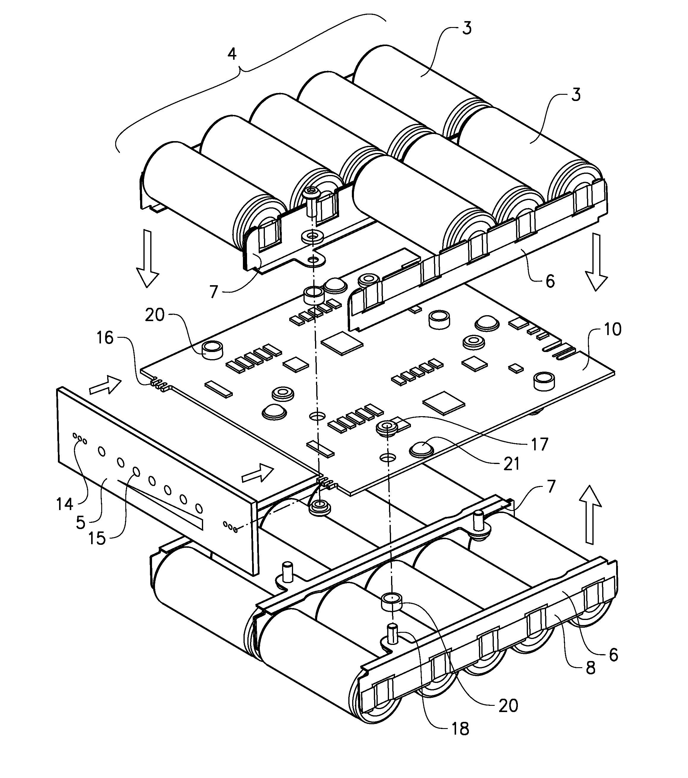
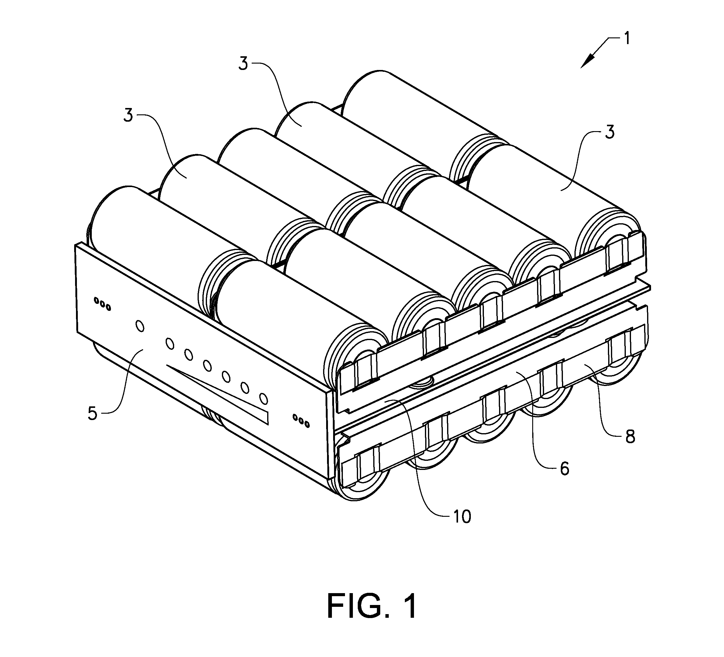
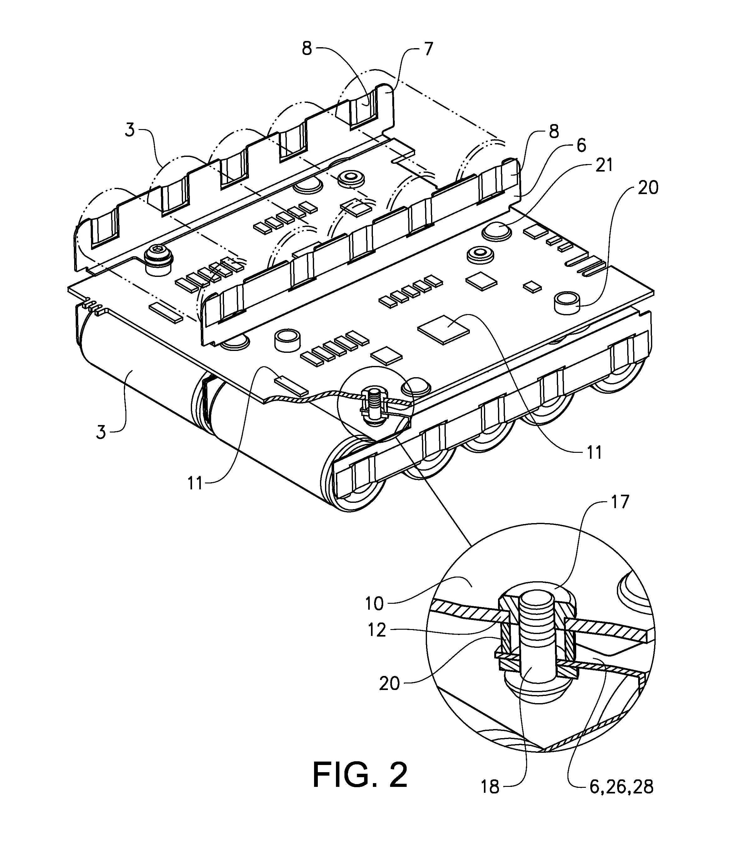
[0038]FIGS. 1-3 show a first preferred embodiment of a battery assembly 1 according to the invention. FIGS. 4-6 show details of the assembly 1.

[0039]In general, the battery assembly 1 comprises, in this example, four similar blocks 4 of rechargeable battery cells 3, a printed circuit board (PCB) 10 provided with an electronic circuit 11 (only schematically shown in the figures) configured to monitor and control the battery assembly 1 and to balance each of the cell blocks 4, and interconnecting means 6, 7, 8, 17, 18, 20, 28 arranged to electrically interconnect the individual cells 3 of each block 4 and to electrically connect the cell blocks 4 to the PCB 10.

[0040]Two cell blocks 4 are arranged on each side (i.e. on each main surface) of the PCB 10. Rigid, electrically conducting spacers 20, as well as resilient spacers 21, are arranged between the PCB 10 and the cell blocks 4 on an upper side (component side) of the PCB 10. Rigid, electrically conducting spacers 20 are also provide...


PUM

PropertyMeasurementUnit
thicknessaaaaaaaaaa
currentaaaaaaaaaa
thicknessaaaaaaaaaa

Abstract

The invention concerns a battery assembly (1), comprising: at least a first block (4) of rechargeable battery cell members (3) that are arranged side by side in at least one row and that are electrically configured in parallel, wherein each cell member (3) has a first and a second electrode terminal (24, 25); a printed circuit board (PCB) (10) provided with an electronic circuit (11) configured to monitor, control and/or balance said first block (4) of cell members (3); and interconnecting means (6, 7, 8, 17, 18, 20, 28) arranged to connect the first electrode terminals (24) electrically to each other and to the PCB (10). The invention is characterized in that the interconnecting means comprises a first supporting metal plate (6) that: extends along said at least one row of cell members (3); is mechanically fixed to the first block (4) of cell members (3); is electrically connected to the first electrode terminal (24) of each of the cell members (3) in the first block (4) of cell members; and that is mechanically fixed to the PCB (10) via a mechanical fixation that also provides an electric connection between the first metal plate (6) and the PCB (10). The invention also concerns a battery system comprising a plurality of battery assemblies of the above type.

Description

TECHNICAL FIELD[0001]This invention relates to a battery assembly according to the preamble of claim 1. In particular, the invention relates to a rechargeable battery assembly for applications requiring a relatively high power, such as driving of vehicles. The invention also relates to a battery system comprising a plurality of battery assemblies.BACKGROUND OF THE INVENTION[0002]Rechargeable batteries of the lithium-ion (Li-ion) or nickel-cadmium (NiCd) type, or similar, have become increasingly interesting as an energy source for driving vehicles (cars, golf-carts, motor-bikes etc.) and other devices, such as boat engines and cleaning machines, as well as for powering e.g. cellular network base stations (together with solar or wind power equipment) in remote areas.[0003]In such applications several battery cells are connected in series and / or parallel in a battery pack or assembly such as to be capable of delivering the required power / current / voltage. Normally, a battery pack of th...

Claims


Application Information

Patent Timeline
Patent Type & Authority Applications(United States)
IPC IPC(8): H01M10/42H01M14/00H01M50/20H01M50/213H01M50/502H01M50/503H01M50/519H01M50/522
CPCH01M2/105H01M2/1072H01M10/425H01M2/206H01M2/202Y02E60/10H01M50/213H01M50/519H01M50/522H01M50/503
Inventor TORTSTENSSON, PER-AKETORELL, MAGNUS
Owner ALELION ENERGY SYST AB
Why Eureka
Try Eureka