Implant Planning for Multiple Implant Components Using Constraints

a technology of multiple implants and constraints, applied in the field of surgical computer systems, can solve the problems of reducing the accuracy of assessing the proper position of implants and reshaping bone, and reducing the surgeon's ability to view and access the anatomy of a joint. , to achieve the effect of convenient placement of implant components

Active Publication Date: 2012-12-06
MAKO SURGICAL CORP
View PDF7 Cites 16 Cited by
  • Summary
  • Abstract
  • Description
  • Claims
  • Application Information

AI Technical Summary

Benefits of technology

[0008]The techniques described herein provide methods, apparatuses, and computer program products for implant planning for multiple implant components using constraints and implant planning using areas representing cartilage. Such implant planning facilitates the accurate placement of implant components of a multiple component implant to fit the unique anatomy of a patient.
[0009]In one aspect there is a method. The method is a surgical planning computerized method for displaying a representation of a bone and a representation of a first implant component with respect to the representation of the bone. The method also includes displaying a representation of a second implant component, wherein the first implant component and the second implant component are physically separated and not connected to each other. The method also includes preventing a positioning of the representation of the second implant component that violates at least one positioning constraint, wherein the positioning constraint is based on the representation of the first implant component.
[0011]In another aspect, there is a system. The system is a surgical planning system including a computer configured to generate a display of a representation of a bone and a representation of a first implant component with respect to the representation of the bone. The computer is also configured to generate a display of a representation of a second implant component, wherein the first implant component and the second implant component are physically separated and not connected to each other. The computer is also configured to prevent a positioning of the representation of the second implant component that violates at least one positioning constraint, wherein the positioning constraint is based on the representation of the first implant component.
[0013]In another aspect, there is a system. The system includes displaying a representation of a bone and a representation of a first implant component with respect to the representation of the bone. The system also includes displaying a representation of a second implant component, wherein the first implant component and the second implant component are physically separated and not connected to each other. The system also includes means for preventing a positioning of the representation of the second implant component that violates at least one positioning constraint, wherein the positioning constraint is based on the representation of the first implant component.
[0018]In other examples, any of the aspects above can include one or more of the following features. A plurality of areas representing cartilage can be calculated, and a positioning of the representation of the first implant component that violates a second positioning constraint that is based on the plurality of areas representing cartilage can be prevented. The at least one positioning constraint can include a rigid constraint between the representation of the first implant component and the representation of the second implant component, wherein the rigid constraint prevents a positioning of the representation of the second implant component that is independent of the representation of the first implant component.
[0028]The techniques for implant planning for multiple implant components using constraints and implant planning using areas representing cartilage described herein can provide one or more of the following advantages. Since each patient's anatomy is unique, having multiple sizes and shapes for the implant components and constraining the positioning of the components with respect to other components and / or the bone allows the system to find a best fit for each patient. The constraints provide information on positioning the components accurately and effectively, preventing improper placement, and enabling the multiple components of the implant to work with each other as they were designed to do so. Multiple types of visual displays further enhance proper placement of the implant components. Further, implant components can be adjusted to account for cartilage representations. A more effective, less intrusive implant planning procedure can be achieved for each individual patient. Implant planning using constraints allows the placement of components that are physically separated and not touching to be optimally placed within a patient's anatomy at locations which ensure the components operate as designed. Optimal positioning of smaller, separate components allows for smaller incisions (e.g., due to the smaller components) and less invasive surgeries.

Problems solved by technology

The invasive nature of the incision results in a lengthy recovery time for the patient.
However, the smaller incision size reduces a surgeon's ability to view and access the anatomy of a joint.
Consequently, the complexity of assessing proper implant position and reshaping bone increases, and accurate placement of implants may be more difficult.
Inaccurate positioning of implants compromises joint performance.
For example, one problem with TKA is that one or more components of the implant may improperly contact the patella, which may be caused by inaccurate positioning of the one or more implant components within the knee.
As a result of anatomical variation, there is no single implant design or orientation of implant components that provides an optimal solution for all patients.
Further, the femoral and tibial components have standard, fixed geometries and are only available in a limited range of sizes.
As a result, the surgeon may be unable to achieve a fit that addresses each patient's unique anatomy, ligament stability, and kinematics.
One disadvantage is that the modular components, once assembled inside the patient's body, mimic a conventional TKA system and thus suffer from similar limitations.
Such implant systems do not enable the surgeon to vary the placement or geometry of each modular component to best suit each patient's unique anatomy, ligament stability, kinematics, and disease state.
One disadvantage of such systems is the determination of the placement of each implant component is not constrained based on the other implant components.
If all implants are planned independently, it is nearly impossible to satisfy all the necessary constraints.
However, CT scans may not accurately determine the articular cartilage surface of the bone.
However, this requires that each point is captured to draw the cartilage surface, which is a timely and computationally involved procedure.

Method used


Image

  • Implant Planning for Multiple Implant Components Using Constraints
  • Implant Planning for Multiple Implant Components Using Constraints
  • Implant Planning for Multiple Implant Components Using Constraints

Examples


Embodiment Construction

[0044]Presently preferred embodiments are illustrated in the drawings. Although this specification refers primarily to knee joint replacement surgery, it should be understood that the subject matter described herein is applicable to other joints in the body, such as, for example, a shoulder, elbow, wrist, spine, hip, or ankle and to any other orthopedic and / or musculoskeletal implant, including implants of conventional materials and more exotic implants, such as orthobiologics, drug delivery implants, and cell delivery implants.

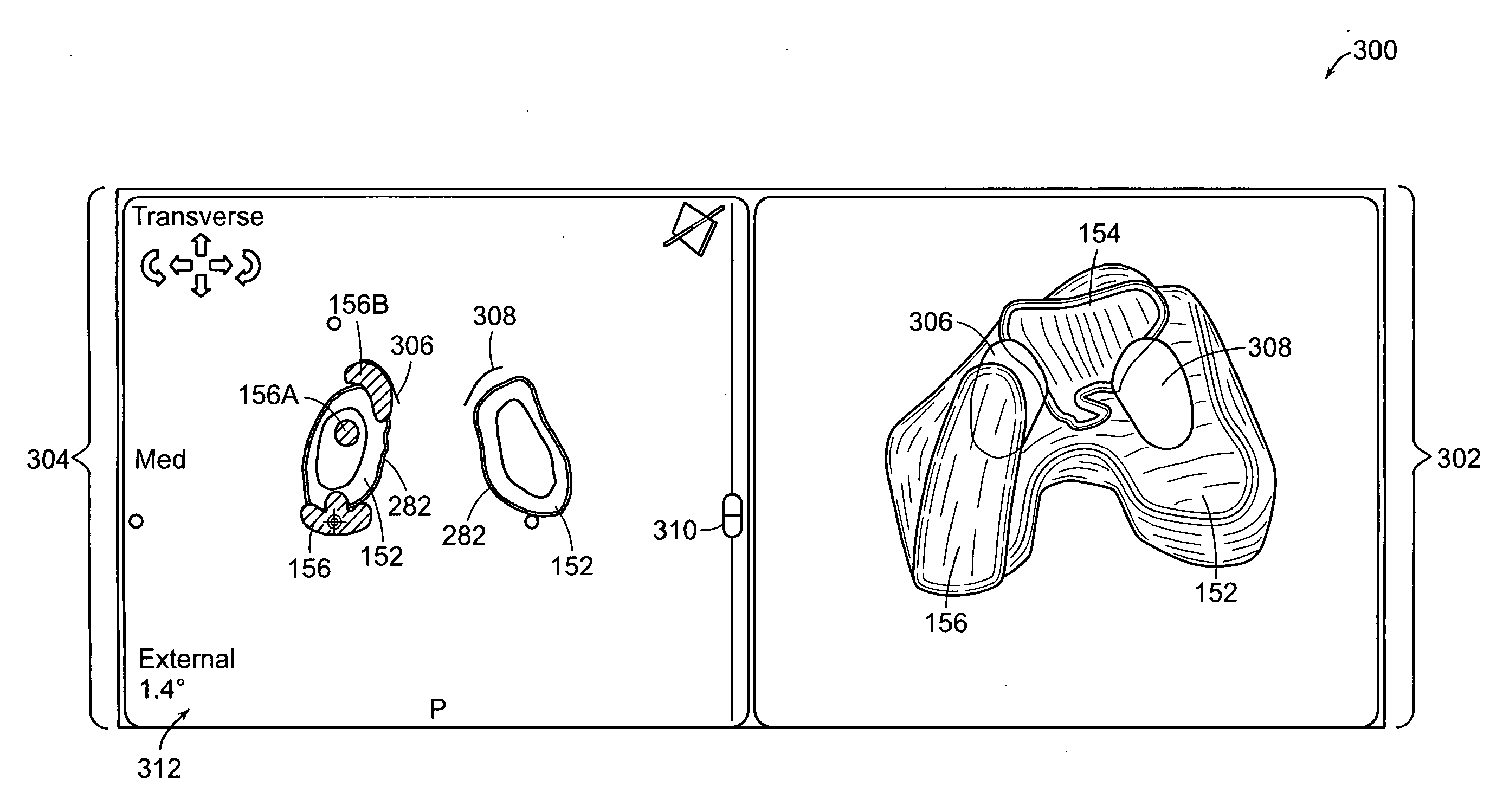
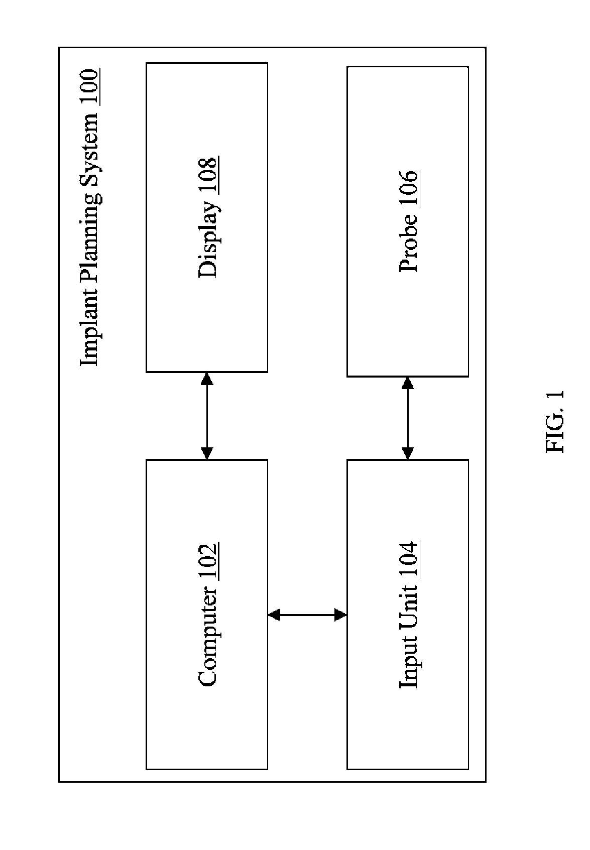
[0045]In general overview, multiple component implant planning is achieved by constraining the adjustment of the individual components of the multiple component implant. Each component can be adjusted based on the constraints, allowing a proper fit for each implant component while preventing improper placement. FIG. 1 illustrates an exemplary multiple component implant planning system 100 according to the present invention. The system includes computer 102. C...


PUM


Abstract

Described are computer-based methods and apparatuses, including computer program products, for implant planning for multiple implant components using constraints. A representation of a bone and a representation of a first implant component are displayed with respect to the representation of the bone. A representation of a second implant component is displayed, wherein the first implant component and the second implant component are physically separated and not connected to each other. A positioning of the representation of the second implant component that violates at least one positioning constraint is prevented, wherein the positioning constraint is based on the representation of the first implant component.

Description

FIELD OF THE INVENTION[0001]The present invention relates generally to surgical computer systems, including computer program products, and methods for implant planning for multiple implant components, particularly to multiple component implant constraints.BACKGROUND[0002]Orthopedic joint replacement surgery may involve arthroplasty of a knee, hip, or other joint (e.g., shoulder, elbow, wrist, ankle, fingers, etc.). For example, traditional total knee arthroplasty (TKA) involves a long incision, typically in a range of about 6 to 12 inches, to expose the joint for bone preparation and implantation of implant components. The invasive nature of the incision results in a lengthy recovery time for the patient. Minimally invasive surgery (MIS) reduces the incision length for a total knee replacement surgery to a range of about 4 to 6 inches. However, the smaller incision size reduces a surgeon's ability to view and access the anatomy of a joint. Consequently, the complexity of assessing p...

Claims


Application Information

Patent Timeline
Patent Type & Authority Applications(United States)
IPC IPC(8): G06G7/60G06F3/048G16H20/40G16H30/20G16Z99/00
CPCA61B5/4504A61B5/745A61B5/4528A61B19/2203A61B19/50A61B2019/502A61B2019/505A61B2019/5255G06F19/321G06F19/3437G06F19/3481G06T7/0028G06T19/00G06T2207/30008G06T2200/24A61B5/4514A61B2034/102A61B2034/2055A61B34/30A61B2034/105G06T17/20G06T2207/10081G06T7/33G16H50/50G16Z99/00A61B34/10G16H30/20G16H20/40
Inventor BELLETTRE, ALEXANDRAARATA, LOUISVAN VORHIS, ROBERTOTTO, JASONWOJCIK, JASON
Owner MAKO SURGICAL CORP
Why Eureka
Try Eureka